What's new

Boolean Subtract and Woodworking

Stuart

Senior Member
I'm trying to find the best workflow for woodworking projects that involve several stages of gluing, cutting/trimming.

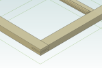
I design the raw pieces and "glue" them together in an assembly
I create the cut/trimmed shape of the glue assembly
I create a boolean of the glued assembly (blank) and the cut/trimmed shape part (tool).

So far, so good.

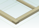
Now I need to repeat this for a couple more iterations.

Not smooth at all, but doable.

Now I decide to change a dimension in the global parameters. This is where the nightmare begins.

I don't see any way to update the booleans. I must recreate them, which then makes a NEW part which then needs to be replaced and repeated for each level. Endless reconstraints later and I'm ready to give up.

Instead of opening a final assembly and having all the intermediate parts and assemblies updated, it becomes a long cumbersome process.

Am I missing the purpose of booleans? They seem only useful/practical for final assembly steps.
Am I missing the right way to weld/glue parts and then continue to work on them towards and final assembly?

I could just make a single final part If I didn't need to have a raw materials list and drawings to build from.

-Stuart
 

HaroldL

Alibre Super User
I'm retired and a hobbyist so my projects are going to be small, not cabinets or furniture. There are probably other solutions and likely better but, what I am starting to do is model each part in its final size/shape and create the final assembly using those parts. Each part has an equation in the Equation Editor to calculate the BF which is then populated in a BOM table on the drawing.

IF some are to be put together as subassemblies I created configurations showing that assembly step then, after setting the display colors to Very Light Background and using Illustration Mode for display, I exported a PNG of each configuration. I imported these images into their own drawing sheet and added assembly notes. On the rest of the drawing sheets I have the final assembly and the parts dimensioned.

I also created an assembly of all the parts of common/same material in a flat shape as if laid out on a sheet for cutting and spaced them to allow for saw kerfs. That helps my to find material for the project and I can arrange the parts as needed to fit them on the sheet. That assembly gets put on its own drawing sheet for printing and I use it for cutting out the parts.

When I cut the parts out I can determine if I need some trim stock based on the material condition and adjust my cuts as needed. And I have the part drawings for any extra work required on them.

If anyone has a better solution that would be nice to know too.
 

Stuart

Senior Member
The fact that a Boolean is a "dumb solid" and not a live design is the problem. Having the "history" of the Boolean doesn't help.
With a dumb solid:
You lose the colors and materials of all the individual components in the Boolean, so the final assembly looks like crap.
You lose all the ability to constrain to any of the features and geometry of the individual parts that make up the assembly Boolean.

To Harold's point, working sort of from finish to start doesn't give these very useful benefits:
Start to finish order verifies the cut and glue order and that the final product can be assembled.
Having each cut and glue stage means you can have drawings with guaranteed correct dimensions for each cut.

The ideal solution (and as a software developer likely not too difficult) is to be able to use an assembly as the base/first feature of another part. It would essentially treat it as a bunch of initial features that are locked. After all, even in a final assembly you can drill down to the very first part, so it isn't really any different.

The only additional advantage I can see of having a "live" Boolean is that I can make a mating part, subtract it from another part and know for sure that the mating part will fit the other part once they're made. Otherwise I have to duplicate the steps to "subtract", and duplicate effort is evil and error prone.
 

HaroldL

Alibre Super User
I think you misunderstood my process or its explanation. I create all my parts in a start to finish process and any subassembly steps are taken into account, whether as configurations or separate subassemblies. And each part is constrained in the assembly, I don't lose that ability. Also, each part does or will have it's own cut dimensions on its own drawing sheet. Otherwise how could the part get cut correctly?

I don't understand your process of having a final assembly as the first step. How do you get that without first creating all its components? Maybe an example would help.
 

Stuart

Senior Member
Mutual misunderstanding ;) I work from start to finish.

I don't model each piece in it's final shape/size. I model them as raw lumber, then add the cuts, assemble them (glue), and repeat until I get to the final assembly. I don't start with a sheet of plywood and cut it into "raw lumber". I skip that starting step, but I can take all of my "raw lumber" pieces and lay them out on a sheet of plywood or stick of hardwood. I don't design that step because the starting stock changes with each project.
 

BobSchaefer

Senior Member
So, I'm trying to understand the whole process you're working through and apparently my brain just isn't getting it. I don't understand why you need the different assemblies locked to get what you want. I also use Alibre to do design my furniture and theatrical sets (as a hobby though on both counts) I don't feel the need to do what I think you're describing.

I work from start to finish as well, usually picking the carcass as my starting point and filling it in, and starting with dimensional pieces and "building"/adding new ones as I build out the design.

So I guess as Harold asked, an example will get stuff straightened out in my head.
 

Stuart

Senior Member
I don't *need* it locked, but I assume that if they added the feature, the initial feature based on the assembly would be fixed like a Boolean, but unlike a Boolean, the internal parts, faces, edges, geometry would be available for constraints as you build up the part.

My current project are some replacement double hung windows for a 100 year old house.

For each sash, I cut rails and stiles which are slightly longer than the final size.
I cut the mortises and tenons in them and glue them together (with a muntin also).

After they are glued, they are trimmed down to final size.

Next, the sash assembly is split into an upper/outside sash and a lower/inside sash. Ideally these variants would be handled with configurations, but another missing feature prevents that.

Each sash variant then get's cuts and pieces glued to them. Simple cuts and gluing can be handled in an assembly, but fitted part subtracts can't.

Then we get to the jamb.

The jamb sides are assembled out of a few simple pieces, although some of it is mirrored.
There is a complex "hole" for the sash spring mechanism. This is to be subtracted by a cnc router. A Boolean subtract with a model of the spring mechanism is the easiest most accurate way to generate the cut in the jamb side. Since each jamb is a mirror of the other, this needs to be applied separately to each one.

Once you have the Boolean, the wood material/color details are lost. When the side jambs are assembled into the final jamb assembly you no longer have the original reference geometry to align/constrain them. The previous work needed to continue the design is lost.

Also, after it's a Boolean you can no longer do an exploded view of the jamb side with the cuts in the pieces that make up with jamb side.

The alternative to the Boolean subtract is to add several complex cuts to *each* jamb side assembly. Much more work than a Boolean subtract operation, and much more error prone.

Once I've worked my way through the jamb I can upload images, but I'm attaching the sash so you can see that part.
 

Attachments

  • trimmed sash.png
    trimmed sash.png
    95.8 KB · Views: 16
  • glued sash.png
    glued sash.png
    128.2 KB · Views: 16

HaroldL

Alibre Super User
I don't mean to take you away from some of your project work but a couple more questions to help me understand the workflow.
Do you mind me asking if you did this kind of work with another CAD program before and are adopting it into Alibre or is this the first time implementing it?

Are the rails and stiles cut long and trimmed on the actual parts or just in the CAD models? If in the actual parts is that because the house is 100 years old there are some minor differences that need to be "fit in place"? Otherwise why can't the CAD parts be created at the finished size?

Could not some of the cuts be part of a configuration that is not shown on the rough cut drawing but used only in the assembly?
 

Stuart

Senior Member
I've used Alibre for 10+ years and I haven't used any other professional CAD software other than AutoCAD 30+ years ago.

The rails and stiles are cut long because the setup of the contour router bits is tricky and never exact (for me). So, by making them 1/4" too long, the glued sash can be trimmed later and all the joints will be exactly flush.

I have two configurations for the rails/stiles and the sash assembly. One with the final trimmed size and one with the rough glued size. I'm doing that part like you said. The sash is workable.

The big problem is with the jamb, mostly involving the spring. The spring has a complex shape that needs to be cut out of the jamb for it to fit. It needs to be cut into the jamb side and a section of the parting strip that is recessed into the jamb side. http://acmeduplex.com/specs_acme_twin.html I have a model of the spring that will be used in CNC to do the cuts in the jambs.

BTW, I'm making 11 double hung windows.
 

Attachments

  • rails stiles muntins.jpg
    rails stiles muntins.jpg
    180.4 KB · Views: 25

NateLiquidGravity

Alibre Super User
You need to use Configurations then with only suppression locked. After each stage you create a new configuration (active) so that any new features added don't effect inactive configurations, but all other changes will update throughout.
 

BobSchaefer

Senior Member
So, the biggest problem you're having is getting the balanced spring configuration modeled into the jambs, does that sound about right? I think I understand the rest of your process and why you do it that way... (not doing production work myself, I've never thought about doing things that way) I'm just trying to make sure we all understand the problem to see what we can do to help out.

Oh, and looking at that web page, wow that does look complicated!
 

Stuart

Senior Member
Nate, I use configurations extensively. Suppression isn't available for features (not parts) in assemblies, so I run into the problem again when I reach the assembly level.

In this project the spring is the biggest problem.

The spring cutout is a thin rectangular recess for the thin metal top, deeper slots on the sides for the bends in the top metal, and a large "oval" for the back. There's also dimples where the crew holes are located. Since it sits across the inner and outside sashes, the parting strip needs to be notched where the spring is located. I'm only cutting the minimal amount for the spring to save material for strength in the jamb.

I've abandon using Alibre for other art projects that had many levels of laminated wood for the same issue.

Here are pictures of an example. These are risers for a staircase, glued but not trimmed for the final fit. They are made of many thin horizontal strips of wood. Using Alibre to "extract" drawings with dimensions for each strip would be a great help. There are over 200 shown. Because the base that the strips are glued to is the same for all the risers, I need to do an assembly at that level. Once I'm at an assembly level, the options for cuts are limited. There are another 4 risers that are much more complicated that I haven't built yet. The treads are also made in a similar fashion. The insets for the handrail are even more complicated. Here's a picture of the open handrail. I would love to have the completed staircase rendered in keyshot. Alibre is good for the initial levels, but when I need to trim an assembly and do the next step, trim again for another step, it becomes more work than doing it by hand. Again, using an assembly just like an initial set of features in a new part would solve all of my problems. I may have missed a feature in Alibre that would help. It wouldn't be the first time.
 

Attachments

  • riser_island_set_completed.jpg
    riser_island_set_completed.jpg
    83.5 KB · Views: 17
  • handrail_installed.jpg
    handrail_installed.jpg
    134 KB · Views: 17

HaroldL

Alibre Super User
You mentioned that the cutout for the spring was prone to errors. Have you checked into using Catalog Features for those cutouts?
And if their installation drawing shows a rectangular cutout are you making it oval to fit the spring as a personal preference? (I would probably do the same thing.)

spring inst.png
 

Stuart

Senior Member
I've only looked at the Catalog, so correct me if I'm wrong.

It appears to be stored in a global library for Alibre and not as a project file. I really dislike the idea of having a very specific part of a single project stored outside the folder for the rest of the project. Also, are changes to the part tracked? If I put a part in the catalog, use it in a project, then update the part in the catalog, will it automatically be updated in the project? If not, it has the same issue as a Boolean where I have to go through all the levels of the project doing manual updates.

In my window design, the jamb is rather thin. The walls of the 100 year old farm house are less than 2" thick (flat planks, no insulation). If I cut a hole through the jamb for the spring body there will be little material left on each side of the spring, so I'm going to do a blind hole the shape of the spring back so that I keep as much material as possible. Keep in mind the instructions online are meant for retrofits, not new windows.
 

HaroldL

Alibre Super User
The Catalog Feature is stored in its library and once it is placed it is just as if you created the feature in the part - there is no link to the library so, yeah, you'd have to update all the where-used if a change was needed. The only thing catalog features do is allow you to reuse existing features that have been created in other parts, that's the Save Catalog Feature command. Unlike a Boolean you are not creating another assembly to use it, so there's that. But I see your point.

In my window design, the jamb is rather thin. The walls of the 100 year old farm house are less than 2" thick (flat planks, no insulation). If I cut a hole through the jamb for the spring body there will be little material left on each side of the spring, so I'm going to do a blind hole the shape of the spring back so that I keep as much material as possible. Keep in mind the instructions online are meant for retrofits, not new windows.
I can see the need for keeping the holes a bit shallow.
 

Stuart

Senior Member
I took a closer look at the catalog. Since the part/feature in the catalog is a snapshot, it doesn't retain the global parameters used with the part/feature. I rely heavily on global parameters and equations to drive the whole project. Approximately 90% of all values used are a global parameter. Too many times I've made a local parameter to only find I need it elsewhere. If there was a button to click to move a local parameter into the global parameters, I'd probably use more local parameters.
 

DavidJ

Administrator
Staff member
Catalog Feature files can be stored anywhere - they are just files. As you confusing with the Dynamic Part Library, which does use a database?

It's easy to tie an inserted catalog feature to a GLP parameter if you wish, then have it change. Yes they bring initial values from their creation instance, but all accessible in the Equation editor. Made easier if the initial instance used descriptive names for the parameters.
 

Stuart

Senior Member
The bit of a test I did with the catalog was that I could export a library to the project folder, but it doesn't automatically update.

When I update a feature/part, it would have to be updated in the library and re-exported. Then the part where I use the feature I'd have to add it again, reconnect all the parameters, reconnect constraints, etc.

The catalog/library seems best for stable part/feature designs. I need a solution that works for my workflow which is very iterative. I rarely know what the final design will be. I start with an idea and do many changes along the way. That's why these manual operations like Booleans are not feasible solutions.

Once again, it all works fine up to the first assembly level. Configurations help, but since you can only have a single configuration active, compound combinations of features have to be flattened to a large number of individual configurations.
 
Top