What's new

Novice Qs and Shelling and Filleting Solids

kcoffield

Member
I try to exhaust the Alibre Documentation, YouTube, and of course help here in that order. It's a bit of a leap from 2D to solid and parametric modeling. I struggle with getting sketches fully/properly constrained, good work flow, editing, and modeling as I'm sure is obvious. Attached is the file from my previous thread. I'm much better with the guided lofting and the model looks ok to me, but it won't shell or fillet.

First, a couple of novice Qs.

1. I used the linear pattern command to copy the lofts (labeled DS & PS runners in the file). Is that the correct (and the only?) way to copy a solid feature to a new location in the model?
2. When you create a solid from intersecting solid features, the combined object is viewed as one solid object if they are all in the active area of the design explorer and any portion/features within the interior of the solid are ignored...correct? I ask because as near as I can tell from the documentation, Boolean is used for importing solids from other files to add or subtract, not fto combine separate features created or already with the same files? Correct?

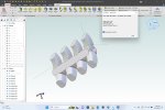
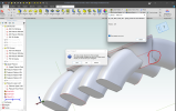
I don't know why it will not shell or fillet. I've read the documentation and search YT, but they only seem to remark about how to use the commands, not how to troubleshoot the problem if the command fails. I'm sure it's probably my (poor) modeling methods but any advice or steer on how to troubleshoot either would be much appreciated. The model and screen capture of the shell and fillet are attached. As always all help is much appreciated.

Best,
Kelly
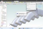
Fillet Fail.jpgShell Fail.jpg
 

Attachments

  • JB Intake Center Section No Fillet or Shell.AD_PRT
    6.3 MB · Views: 8
Last edited:

HaroldL

Alibre Super User
Just looking at your screen shots it looks like you have three failed Shell features. Shell acts on the entire model so adding additional shells may not give the results you want. Why were the additional shell features added?

What is the status (error message) of the failed shell features?
 

kcoffield

Member
Just looking at your screen shots it looks like you have three failed Shell features.
Three failed shell features? What/where on the screen shot is that identified? As far as the fail, I only see what is in error the dialogue box.

LOP_TWK_NO_VERT: no solution for a vertex......... are these supposed to be labels or contractions of labels or some clue to the failed features? I can't identify the corresponding features in the design explorer. How do I do so?

If you mean the failed Shell 49 and 50 in the fillet fail screen capture, those are just because I reran shell with different faces deleted.

What is the status (error message) of the failed shell features?

If I can find them, I can check status.

Best,
Kelly
 

Joseph_L

Administrator
Staff member
I'm seeing areas where the runner is spilling onto the bottom face. If you're able to alter the design slightly so the runner edges stay on the side face(s), fillets will be a lot more straightforward. Shelling to a thickness without sharp edges (because you added fillets!) and to a thickness less than the minimum radius of curvature make shells more likely to succeed. You probably know that you can start with a very small fillet radius and then work larger until you can see where the fillet stops to a gage what might be affecting the fillet.1694041552390.png
 

HaroldL

Alibre Super User
Three failed shell features?
Oops, I misread the fillet as shell. :oops:

If you mean the failed Shell 49 and 50 in the fillet fail screen capture, those are just because I reran shell with different faces deleted.
if you are running different design scenarios and create a shell feature and you want re-shell with different faces deleted you should suppress the first shell before creating the second one. That may be something you could use Configurations for, if your version of Alibre has that capability.

f I can find them, I can check status.
Right click on any feature in the Design Explorer and select Status from the pop up menu.

LOP_TWK_NO_VERT: no solution for a vertex.........
I think these are more suited for programmers to decipher since they make no sense at all to designers. I've seen that one on more than a few occasions and the only thing I get from it is that something didn't work.
 

kcoffield

Member
I'm seeing areas where the runner is spilling onto the bottom face. If you're able to alter the design slightly so the runner edges stay on the side face(s), fillets will be a lot more straightforward.
Shelling to a thickness without sharp edges (because you added fillets!) and to a thickness less than the minimum radius of curvature make shells more likely to succeed.

That bottom plenum surface actually did protrude below the runners. I didnt like it and wanted the interior floor even with the runner opening after shelling so I changed it. I think the old plane and sketch is still there, just not used, but it's only about 1/8" below the runners. It would shell or except radii then either but I was using .375" radius so it will still be smaller than the height of the step to that surface. Either way the position of that feature is easy to change to see if it's the culprit.

You probably know that you can start with a very small fillet radius and then work larger until you can see where the fillet stops to a gage what might be affecting the fillet.

I will experiment with the radius size. The wall thickness must be .25" (or near) on the final part but certainly can be altered for experimentation.

Right click on any feature in the Design Explorer and select Status from the pop up menu.

The 10 solid features that make the part were all without error after they were made. I will check the status of every feature tomorrow.

Thanks for the observations fellas.

Best,
Kelly
 

HaroldL

Alibre Super User
I will check the status of every feature tomorrow.
If a feature has no error (shown Red in the DE) you don't need to check its status. I only check status on the features that fail and show up Red in the DE. In the screen shot it appears you have 'Show popup on errors' selected so it will reveal its status as soon as it fails.
 

kcoffield

Member
Well, I've tried all the suggestions and no joy on filleting or shelling. Here's what I've tried.

First, I did lower the plenum floor to get rid of the potentially problematic areas circled in Joseph's post. No errors in features used. The only errors that exist on the DE are the deleted faces from features. I assume they have error status because the feature that created them is suppressed. Their status is restored if the parent feature is unsuppressed. I can post the file if needed.

Filleting:

1. Selecting all 8 runners and the lateral plenum wall, it would not fillet at any fillet thickness. I tried down to .010" radius.
2. Think the complex intersection of the two front runners and the plenum wall where Joseph commented in the previous post that he might see a stray surface (I could not detect any), I selected just one of those runners and the plenum lateral surface. Same result; would not fillet any radii but threw a different error code than previous fails.
3. I selected one of the other interior runners that had a less complex intersection with the plenum wall, and the plenum wall. Same result; would not fillet any radii but threw yet a different error code than previous fails.
4. I examined the plenum loft and noticed the lateral walls were actually concave. So I played with the loft setting so the lateral surface of the loft was straight instead of concave. Same result; would not fillet any radii but threw yet another error code than previous fails.

Since I couldn't fillet the model, I doubted shelling would be successful based upon the previous remarks, but tried anyway.

Shelling:

1. I removed the rectangular faces and the top of the plenum. It would not shell inward or outward at any thickness down to .010".
2. I tried the alternate method taught in this video:


............converting to a surface and trying to use the thicken command. It would not the thicken inward or outward at any thickness down to even .001".

I may be out of bullets on filleting & shelling, unless there are other suggestions. Disappointing. The thought of creating and entirely separate solid to subtract from the existing model in order to create a 1/4" wall version of the model, while possible, is not something that garners much enthusiasm and I suspect there may be new learnings and obstacles to conquer. I have a lot of projects similar to this one and would probably rather invest my time figuring out how to make models that would fillet and shell, with parametric attributes for the changing features.

I could probably use the surface I created from the existing solid, split at the midplane/parting line to make my CAM programs and CNC the pattern for that part as is. It would be suboptimal, but the fillets on the external surface would happen naturally as a function of the of the diameter of the ball nose cutter selected. For the interior machining, I would simply reverse the surface face, and to produce 1/4" wall, I would just specify a .25" roughing clearance. There would be a couple other work arounds required, but doable I think.

It's hard for me to get excited about compromising designs so I can model them, at least within reason. I need to be able to model the features that make the parts function and perform properly. It's a pretty ambitious project for a novice. -My reach exceeds my grasp at the moment but am willing to invest the time if success can be achieved.

Best,
Kelly

Faces removed Surface.jpg
 
Last edited:

Joseph_L

Administrator
Staff member
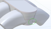
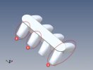
I checked the updated part you uploaded. There is indeed a problem face in the circled area. Other runners were able to be filleted as pictured, but that face can block both fillets on that runner and shells on the part until it is eliminated.1694113067152.png
 

HaroldL

Alibre Super User
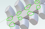
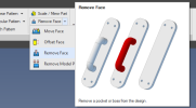
Kelly, one thing you can try is to use Remove Face on the small faces that are at the end of lofts that do not align with the surfaces of the plenum (indicated in the Green sketch in the image). Once the face is removed the adjacent faces should blend into the plenum surface.

1694113815806.png

One more thing I have found to help when Shell or Thicken just won't work with fillets is to shell without any fillets. Then apply the fillets to the outside and inside as separate features after the shell. That will give you the ability to adjust the inside fillets to a value that will work although they may not be and exact offset from the outside fillet. It will be more of a blend on the inside to give rounded edges, and, in the case of your manifold may be within tolerance of any molded/cast part.
 

kcoffield

Member
I checked the updated part you uploaded. There is indeed a problem face in the circled area. Other runners were able to be filleted as pictured, but that face can block both fillets on that runner and shells on the part until it is eliminated.

You're a cruel man to show me that sir. :D

.......But, that's an old version of the model, not the one I used this morning in the post #9 above. The model I used does not contain that face. The new intersection is different in that location and does not contain that edge (which is why I couldn't find what you were referring to), but it's more complex and may pose other problems.

Updated Model.jpg

The new model is attached. I tried to clean things up a bit. The three rearward runners are identical on each side. The front two are driven off their own unique guide curves. The loft for the plenum has been edited to change the lateral surface of the plenum from being slightly concave (as in the version you filleted and noted above) to a straight(er) surface which may very well in itself have eliminated that stray surface.

What I don't understand is how you got it to fillet. I tried to fillet just one of the interior runners to the plenum and similarly failed with all radii and attempts. What did you do to get those portions of the model to fillet? I run v25 Design Pro.

Best,
Kelly
 

Attachments

  • JB Intake Center Section Surface.AD_PRT
    5.9 MB · Views: 8
Last edited:

kcoffield

Member
Kelly, one thing you can try is to use Remove Face on the small faces that are at the end of lofts that do not align with the surfaces of the plenum (indicated in the Green sketch in the image). Once the face is removed the adjacent faces should blend into the plenum surface

Not sure I understand which small faces you are referring to. By way of the example pictured in your post or specific features of my model not depicted in that image/post? To isolate the issue, when I try to fillet just one runner to the plenum, I remove the rectangular face at the opposite end of runner, then select only the lateral surface of the plenum and the remaining surface of the runner, each which display and select only as one surface each. Wont that limit the fillet being commanded to just the junction of the that runner and the lateral plenum face?

One more thing I have found to help when Shell or Thicken just won't work with fillets is to shell without any fillets. Then apply the fillets to the outside and inside as separate features after the shell. That will give you the ability to adjust the inside fillets to a value that will work although they may not be and exact offset from the outside fillet. It will be more of a blend on the inside to give rounded edges, and, in the case of your manifold may be within tolerance of any molded/cast part.
I'd certainly be willing to apply radii afterward but as I remarked in post #9, I can't get the unfilleted part to shell or thicken.......period.

Best,
Kelly
 
Last edited:

HaroldL

Alibre Super User
Not sure I understand which small faces you are referring to. By way of the example pictured in your post or specific features of my model not depicted in that image/post?
I was referring to the image that Joseph had posted in his reply in post #10. But as you noted, the model has been updated to remove that issue.
 

kcoffield

Member
I was referring to the image that Joseph had posted in his reply in post #10. But as you noted, the model has been updated to remove that issue
Ahh I see........if you have an area that you suspect may be problematic just subtract it from the faces/features being filleted. Good for future reference........still stuck.

Best,
K
 

HaroldL

Alibre Super User
I think there is an issue with the lofts. :confused:

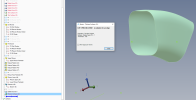
As an experiment for trouble shooting the issue, I downloaded your latest model and cut away everything except for one lofted port. I then used Delete Face to remove all faces except for the outer loft surface. As you can see in this image, when I use Thicken Surface on the remaining surface it failed with the displayed status.

1694122541567.png


I should also point out that I got the same status message when I tried to Shell the same part by selecting the same surfaces to be removed. This seems rather odd. I even looked at the master loft that was patterned to see if changing any setting in it, like minimize twist, may allow a successful shell or thicken but nothing helped.

1694122926578.png

I'm thinking that it may be beneficial for you to submit this model to Support for analysis. One would think that the model should shell or thicken when stripped down to this basic feature. :confused:

I'll add a couple of observations - I noticed that you had several Delete Face features at the top of the DE tree. When you are deleting faces it isn't necessary to run the tool for each face you want to delete. You can just edit an existing Delete Face feature and add more faces to that one for removal.
 

kcoffield

Member
As an experiment for trouble shooting the issue, I downloaded your latest model and cut away everything except for one lofted port. I then used Delete Face to remove all faces except for the outer loft surface. As you can see in this image, when I use Thicken Surface on the remaining surface it failed with the displayed status.

Yes, I had the same experience and I recognize the content of that error log. What I don't understand is how Joseph succeeded in getting it to fillet because the fillet command seemed to be throwing up on all my geometry as well.

I'm thinking that it may be beneficial for you to submit this model to Support for analysis. One would think that the model should shell or thicken when stripped down to this basic feature.

I just own v25 with no maintenance contract. Would the submittal be considered?

I'll add a couple of observations - I noticed that you had several Delete Face features at the top of the DE tree. When you are deleting faces it isn't necessary to run the tool for each face you want to delete. You can just edit an existing Delete Face feature and add more faces to that one for removal

Understood. Most of those deleted faces are artifacts from my thin extruding a 2D spline normal to the XY Plane and then trimming away all but the zero-thickness face/surface that intersected the cylindrical parting line surface, so I could project a 3D sketch to produce the 3D runner guide curves. Some of those faces were hard to get at without deleting some before the others. Creating the guide curve in that manner was a importantlearning but a hard fought/won battle on the learning curve.

Best,
Kelly
 
Last edited:

kcoffield

Member
As an experiment for trouble shooting the issue, I downloaded your latest model and cut away everything except for one lofted port. I then used Delete Face to remove all faces except for the outer loft surface. As you can see in this image, when I use Thicken Surface on the remaining surface it failed with the displayed status.
Harold. do you remember which one of the eight runners/lofts that was you isolated for this test?

Best,
Kelly
 

HaroldL

Alibre Super User
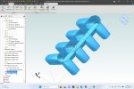
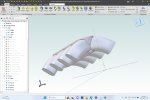
I actually tested on different lofts, as this image shows there were three sections tested.

tested lofts.jpg

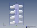
Here's a screen shot of the sketch used for the third and last one. I just sketched on the top surface and did an Extrude Cut through all.

last sketch.jpg
 
Top