What's new

Novice Qs and Shelling and Filleting Solids

kcoffield

Member
I have some other commitments for the next couple days so won't have much time to devote to it.......which is probably good for me to step away from it and come back with a clear head. I've been CAD binging a bit for the last four days thinking I'd rip off the band aid in my cycles of learning, but where I got to feels more like I removed tourniquet. :mad:

It's probably something silly I've done somewhere in the model construction because I dont know any better. One thing I will try when I get back to it is to suppress or delete all the runners so only the central plenum loft remains, and see if that will shell or thicken. Then add a simple round boss to it and see if that will fillet.

Very early in the post I commented I used the linear pattern command to copy (what you identified as loft #3) to the two positions rearward. Then I did the same on the other side. I would have mirrored the first three but couldn't figure out how to offset them into position after I did so.

Anyway, it took me a while to figure out the number of instances you specify in the linear pattern command must count/include the original object. I started with two instances which worked and correctly displayed the three runner/lofts, but afterward when I would try to use the original loft for something, Alibre reported the object was no longer available even though it displayed and its status did not display as being in error in DE. Then I figured out I needed to specify 3 instances to include the original loft in the linear pattern and all seemed well. I have no idea if this has anything to do with the problems shelling/filleting......probably not. There were no comments to my original question if this is the usual way of copying solid features within the model.....just thought I'd mention it just in case.

Best,
Kelly
 

Ex Machina

Senior Member
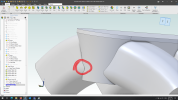
I haven't checked the entire model but for sure that is not going to shell...
1694192615179.pngP.S. I just noticed that Joseph has already point that out. Sorry for that Joseph.
 
Last edited:

HaroldL

Alibre Super User
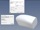
After further trouble shooting your model I think the issue is that neither of the runners will shell individually. I rolled the model back to the PS Runner and, with the DS Runner suppressed, I tried to shell with the two end faces selected for removal and it failed.

1694197228669.png


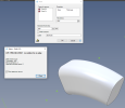
I then rolled back to the DS Runner (unsuppressed) and got the same results with both end faces selected for removal.

1694197350772.png

So there is something about the two runner lofts that will not shell. I analyzed the three sketches in each runner and they passed inspection. I just don't know why it cannot find a solution for an edge in either of the runners.
 

Ex Machina

Senior Member
.... It's a bit of a leap from 2D to solid and parametric modeling. I struggle with getting sketches fully/properly constrained...

Best,
Kelly
The problem seems to be the centerline.

I think we need to redesign this model from scratch. There are too many issues. For example, no sketch is fully defined. Another problem are the 2 sketches that make up the main plenum body loft. They both have overlapping and degenerate features. The "DS PW Centers" sketch is underdefined which means that if you click and drag one point all of them move and it becomes a mess.

Finally, the centerline is made from a projected edge created by intersecting surfaces. These surfaces were made from extrusions that had faces removed to be made into surfaces. But then, crucially, the extrusions where suppressed. Which means that they are no longer there to be used to create anything. So, everything has degenerated.

Suppression does not work like AutoCAD. If it's suppressed it is erased. It only shows there so that you don't need to redefine it if you need it back for some reason (i.e. configurations). If you then use something that came up from that suppressed featured, you are asking for trouble. Evident of that is that the delete surface features are all throwing errors, as well as the trim features that eventually created the centerline. Using unconstrained sketches on top of that degenerate centreline, did nothing to help.

It's the "Back to the Future" problem. Parametric software follows a time order. If you use something to create something else and then delete it, the child feature can no longer reliably EXIST. it's like Marty McFly's parents not getting together, which then means he phases slowly out of existence. That is what has happened with that suppression. It's not like hiding a layer in AutoCAD. In parametric software, there are no layers. Everything counts. And everything in a sketch can move around in a coordinate system unless geometric definitions and dimensional values are used to pin it down (i.e. reduce the Degrees of Freedom to 0).

So the centreline was:

Created by extrusions-->
-->That had faces deleted to turn them into surfaces-->
-->Which were then trimmed to produce edges-->
-->Which were then projected into a 3D sketch to create the centreline.

If you erase the first part of that chain, which is what suppression does, everything falls apart. It's like building a skyscraper and then trying to demolish only the first floor.

At this point it's faster to redesign than to salvage that part. Maybe one of us can get on a video call and help Kelly with it. I could potentially find an hour or two tomorrow morning (GMT+02:00 timezone).

P.S. The middle profile per loft and the centreline might not even be necessary with proper use of the tangency multipliers. But I am not sure about that yet.
P.S.2 Making extrudes and then deleting faces to turn them into surfaces and then trimming them is not really standard procedure. It's a type of "CAD Black Magic" that Joseph makes look very easy but is actually beyond Pro level. It is best avoided until you are really sure how everything works in Parametric CAD.
 
Last edited:

kcoffield

Member
Thanks for that thorough and thoughtful commentary ExM. There's a lot for me to digest in that commentary. Let me do some home work and I'll be back.

Best,
Kelly
 

kcoffield

Member
At this point it's faster to redesign than to salvage that part.

This doesn't concern me. I think I've done so 4 times now, so a fifth would be no problem.

I haven't checked the entire model but for sure that is not going to shell......

I just want to make sure we’re all looking at the same revision of the model attached in post #12 because you also refer to the same edge as Joseph that as near as I can tell, that feature does not exist in the updated model. Though I felt I made some improvements in this revision, I still think the rest of your comments and observations apply to this revision as well.

Maybe one of us can get on a video call and help Kelly with it. I could potentially find an hour or two tomorrow morning (GMT+02:00 timezone).

This is a most generous offer but to make good use of your time, it seems I have quite a bit of homework to do first. I am GMT -06:00. What kind of video conf software do you use?

Without doing a whole bunch of quotes to your specific observations (which I very much appreciate by the way) in summary I would say I need to develop a much better understanding and command of fully defined sketches and the differences between suppressing features, deleting vs trimming surfaces, and sometimes I just merely wanting to hide these features. On the subject of fully defining my sketches, I will circle back through the introductory Alibre sketching tutorials, but I think this will be my fourth time doing so and apparently I'm not adequately understanding the teaching. A couple examples of my frustration that you refer to from the model attached in Post #12:

I created the sketches “Upper Plenum Perimeter” and the “Plenum Upper Loft” in the exact same manner with the two corner rectangle and fillets. They are dimensionally identical just in different planes. One displays as fully defined and the other is not even though the features of each sketch are identical and appear to be identically constrained. The only difference I can notice is one of the vertices of the original unfilleted rectangle is missing and I don't know why. Any attempts I make to further define that sketch is refused as being unallowed or overconstraining. Same goes for the “Lower Plenum Perimeter”. So I gave up and moved on with the model because the loft seemed to execute and reported no error in DE, but it certainly wasnt for lack of trying.

I have similar issues with all the rectangular port Window skecthes used for the various the runner lofts. Other than the end points, I have no idea how one would contrain and get a 3D Spline fully defined.

The problem seems to be the centerline.

You can say that again.

So the centreline was:

Created by extrusions-->
-->That had faces deleted to turn them into surfaces-->
-->Which were then trimmed to produce edges-->
-->Which were then projected into a 3D sketch to create the centreline.
P.S.2 Making extrudes and then deleting faces to turn them into surfaces and then trimming them is not really standard procedure. It's a type of "CAD Black Magic" that Joseph makes look very easy but is actually beyond Pro level. It is best avoided until you are really sure how everything works in Parametric CAD.

I'm open to other methods but I spent nearly 3 days trying to come up with a 3D spline that connected the centers of the of loft sketches, and absolutely zero would be accepted by Alibre as a suitable guide curve for a loft. I then used the method taught in Joseph's videos though perhaps I didnt execute them properly trimming and deleting, but the key to the 3D guide curves was creating the sketch planes for the loft faces with the plane along a sketch command, because this was the only method that would position the sketch in a manner acceptable to Alibre loft using a 3D Pline guide curve. I have the whole other thread as long as this one that came to this conclusion. Do you have another method in mind?

Bottom line on this model is:

The port and plenum windows need to be at precsribed (or very close) positions in 3-space. The loft faces must differ a prescribed amount in cross sectional area. The lofts between them need to be guided by 3D splines that are relatively streamline as the internal vloumes will direct a fuel/air mixture at sonic flow. The methods used approximate all of this and will undoubtedly need further refinement, but if I can't succeed with the simplified approximations, there's no hope for refinement.

There are too many issues. For example, no sketch is fully defined. Another problem are the 2 sketches that make up the main plenum body loft. They both have overlapping and degenerate features

Is this because you know it's an outcome of the undefined sketches and absence of deleted faetures, or is there something else directly you can see that tells you so?

Best,
Kelly
 
Last edited:

Ex Machina

Senior Member
Hey Kelly,

I use Teams, Zoom, Skype and Google Meet for video calls. As for fully defining sketches, I think Alibre help will not help you. Nor will any other CAD system help file. I have seen videos on YouTube before on the topic of going from AutoCAD to a parametric CAD, but I cannot vouch for their quality. The goal of sketching is different basically in Parametric software than 2D sketchers or even 3D non-parametric modellers.

I haven't got anything scheduled next week in terms of calls. Let me know when you'll ahve some time and we can schedule a 1hour call. Availability is 10am - 2pm GMT+02:00.

As for the plenum sketches, I went ahead and used Analyze Sketch. But the entire approach is not strictly correct. It is clear that you think that when you see a sketch entity in the correct place you consider it to be OK. But it's not. In parametric CAD, you can think of sketch entities as the result of mathematical functions in the 2D plane of the sketch. If a line is not fully defined, that means that its "equation" can be solved to produce many lines not only one. And then you need some additional constraints, (with a bit of a stretch you could call them boundary conditions) to select a particular linear segment from that line to be your linear sketch entity.

It is a lot easier than I make it sound above. And orders of magnitude faster than AutoCAD or any 2D sketcher. But you need to get in the correct mindset for it. After that, it'll be a breeze.
 

JimCad

Senior Member
I think that for a novice Kelly has done VERY well. Autocad people usually struggle to understand constraints and methods for 3D Cad. Once it "clicks" in their heads they're usually good though.
Well done for Effort Kelly.
Well done Konstantinos and all of you for helping.
Jim
 

kcoffield

Member
Well done for Effort Kelly

Thanks Jim. I try not to let the fact I don't know what I'm doing get in the way of me doing it anyway :).

I've made a handful of other models in Alibre. This one was a bit more ambitious for my level, but I've found that's how I learn. Persistance and the ability to suceed in achieving the end product keeps me motivated.

I went through a similar learning curve with CAM and GCode for CNC. I use these models to make real automotive castings that are cast aluminum, machined, and put into service, so there is still quite a ways to go once I have a model, but the end is rewarding. I suspect the previos models had similar problems that have been noted above but werestill able to be seen through to fruition as working parts.

Here was a recent project. I'm the admin at a home casting forum so my videos are more geared towards practical processes for making larger more complex castings in a home/hobby environment. There are plenty more related videos on my channel and more to come if you're into that. My real habit is motorosport and all of this is just a means to an end.

.

I'll stick with it and post up my progress occassionally. Thanks to all who have offered assistance.

Best,
Kelly
 
Last edited:

Joseph_L

Administrator
Staff member
I agree, it's looking like regular loft is easier to deal with. I made one of many possible workflows to do the runners in a way that converts the centerline loft into a regular loft. This is more surface heavy than I would prefer, but it fillets and shells.
 

Attachments

  • Runner.AD_PRT
    8.9 MB · Views: 3

kcoffield

Member
Thanks Joseph. I'll take a look at that and see if I can understand the construction. Things should be as simple as possible, just not simpler.

In simplest terms, there are only four (three without a guide curve) sketches/shapes needed to produce the model. What I call the port and plenum windows which are the loft faces, and the plenum opening.

It's really only two solids. A linear pattern of 8 of the single loft (runner), and the plenum extrusion. As opposed to straight extrusion, I can make the plenum loft look just like that in my model merely by extruding the Plenum Opening sketch with draft.

Now locating and constraining all these shapes in 3-space is an entirely different matter.........at least for me at my current level of skill and understanding.

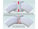
I did get the model to fillet, but I had to change the plenum to being a straight extrusion and increase it's height above and below the intersection with the runners so the full radius of the fillets had surfaces to land on. Through process of elimination with what surfaces I chose to fillet, it wasn't so much the shape of the plenum itself that was the problem but the overlapping vertex at the intersection with the front two runners that was causing the fillet to fail........even with all the incompletely defined sketches and error features in the DE caused by suppression of parent features.

Comments for Konstantinos 1.jpgComments for Konstantinos.jpg

Thanks again for the file Joseph. I'll stick with it.

Best,
Kelly
 
Last edited:

kcoffield

Member
I made one of many possible workflows to do the runners in a way that converts the centerline loft into a regular loft. This is more surface heavy than I would prefer, but it fillets and shells.

I can't open it because it's v27 and I am v25. :(

Best,
Kelly
 

kcoffield

Member
Hi Kelly,
you can download V27 and use it only as a Cad viewer to see the file prepared by Joseph...am I right?

I posed that quesion in live chat on Ailbre site and here was the reply.

Q >I own a Alibre Design Pro v25 license. Can v27 be downloaed for free and/if used only as a CAD viewer? Is that true?

A >I'm afraid that's not true. To have access to v27 you would need to renew your maintenance

Maybe it's true if you dont already own a license?.....dunno. Lapse fees are waived at the moment so I think I'll just buy the 1yr maintenace contract and get up to date.

Best,
Kelly
 
Last edited:

HaroldL

Alibre Super User
It's the "Back to the Future" problem. Parametric software follows a time order.
Konstantinos, I haven't heard that one before but it's a good analogy.
Also taking a deeper dive on the design was a good move. I only used the Analyze Sketch tool to check the sketches for completeness. But the fact that the loft was created proved that they were complete, just not completely constrained, as you pointed out.

The use of extra geometry to define 3D sketches has been discussed before on the forum. I think the method that Joseph uses by deleting faces and then using the remaining surface edge as a source for the guide curve has merit. The thing to remember is DO NOT suppress the originating solid feature. That will cause the subsequent Delete Faces to fail. The thing to do is to Hide the surfaces in the Surfaces section of the DE. That should maintain the surfaces association to their solid parent and the resulting 3D sketch IF maintain association is selected..

I use Teams, Zoom, Skype and Google Meet for video calls.
Good on you for offering to give some online/personal help for the issue Kelly is having.
 

Ex Machina

Senior Member
Hey Harold,

Thank you for liking my analogy. Basically, it's what I say to everyone that I try to teach Parametric CAD to. Recently, I've started feeling old because not everyone has seen the film... lol

As for the surface technique. It's amazing. I was completely blown away when Joseph showed it in the video. I had never thought of using Alibre like that. But it's a bit advanced, not for beginners. That's what I tried to say. But I think it showed all of us the real power of Alibre, that video from Joseph.
 

kcoffield

Member
A huge shoutout and sincere expression of my thanks to Konstatinos of Ex Machina for spending time with me today via web meeting. -Truly a kind guesture that went above and beyond.

I have a lot to digest from that call but one alternative discussed was a version that utilized drafted sweeps. I was quickly able to generate a model based upon such below, and it was clearly the farthest I've been able to take it thus far, through filleting, and there are many useful parametric aspects to the model.......though still will not shell or thicken.

Drafted Sweep Filleted Surface.jpgDrafted Sweep Filleted.jpgDrafted Sweep Filleted Surface.jpgDrafted Sweep Filleted.jpg

I have quite a bit more to digest from that call and put into practice. I will not be able to do more with it for about a week, but rest assured, there will be a sequil. Thanks to all who have helped and commented thus far.

Best,
Kelly
 
Last edited:
Top