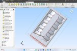
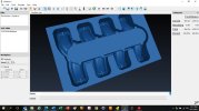
What's new

Novice Qs and Shelling and Filleting Solids

kcoffield

Member
I'm back in my action and to my credit, I've found a couple other approaches that don't/won't work. ;)

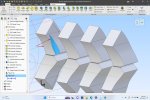
Not sure why the pictures in the post above didn't display but first file attached below uses a drafted sweep for the Runner features. I really like this model because I can easily change many of the important features, but, the sweep twists and that will make 3-axis cnc machining this model much more problematic, It would be so much more practical if the lateral faces of the sweep could be constrained to be vertical (see corresponding picture). The documentation seems to suggest selecting rigid feature for the sweep will cure this and it also indicates you can add draft after doing so, but when I do, it throws an error indicating a drafted sweep can't be rigid. Am I misinterpreting the documentation in this regard? Is there another way to keep the sweep from twisting? Constraining the sides of the sweep sketch profile doesn't seem to prevent the twist either.
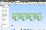
Fully Filleted Sweep NonVertcal Runner Face.jpg

Best,
Kelly
 

Attachments

  • JB Center Drafted Sweep Runner Plenum Floor Cut.AD_PRT
    4.7 MB · Views: 9
Last edited:

kcoffield

Member
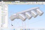
So, I took another approach that is admittedly a bit more of a 2D rather than 3D modeling mindset, but I thought it was sure to keep the runner sweep surfaces correctly oriented. It's basically just a combination of a simple sweep, extrusion and some extrude cuts. But, although two of the four corners fillet, the one shown in the picture will not fillet properly and the other errors. Same thing happens on the opposite side. Any comments on why and how to correct it would be appreciated. If I could get the fillet to generate I'd include them in the linear pattern and get on with the rest of the model.

Failed Fillet Sweep Extrude Rev 2.jpg

Edit: I do note that the model seems to have two faces that meet where the fillet terminates and I surmize that's because it's at the interesection of the extrusion and sweep, and either the spline isnt tanget at that intersection or maybe the radius becomes to small at that face? But this doesnt seem to bother the fillets on the top corners.....?

The short extruded section is there to insure the cross section is rectangular when it gets sectioned/extrude cut at 45 degrees.

Best,
Kelly
 

Attachments

  • JB Center Sweep Extrude Rev 2.AD_PRT
    922.5 KB · Views: 1
Last edited:

kcoffield

Member
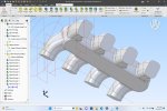
I've probably worn everyone out on this one, but think I may now have something usable. It's a variation of the file immediately above. I extended the extrusion that forms the straight section of the runners to eliminate the area that was corrupting the fillet, and changed the order of work flow filleting before I made the final extrude cuts that position the rectangular port faces. It's not elegant work flow but appears to suit my purposes.

The sides of the runners are now vertical so it should machine much more practically. It filleted nicely but still won't shell or thicken. I think I'm going to give up on shelling for the time being. It's probably more my modeling technique but as I experimented, I can only get that shell command to work with relatively simple geometry. For the inside surfaces I think I'll try to modify this model accordingly to produce another solid and try using Boolean subtraction to create a 1/4" wall thickness model and the inside surfaces.

-Thanks for the help.

Filleted With Vert Lat Sides.jpgFilleted With Vert Lat Sides Bottom.jpg

Best,
Kelly
 
Last edited:

albie0803

Alibre Super User
It's great to see what other people achieve. It lets you know what's possible and sometimes sparks ideas about approaches you wouldn't have thought about.
 

kcoffield

Member
I'll take a look tomorrow. If you could upload the file, that'd be nice.
Attached. Like I said, not elegant but progress.
It's great to see what other people achieve. It lets you know what's possible and sometimes sparks ideas about approaches you wouldn't have thought about.
Thanks Albie. I'm not sure how much of an achievement it is but it has definitely been a learning experience........still much to learn.

Best,
Kelly
 

Attachments

  • JB Center Sweep Extrude Rev 3.AD_PRT
    3.5 MB · Views: 2

HaroldL

Alibre Super User
Have you isolated any of the runners to see if it will shell? I recall that the runners were failing to shell in previous versions of the design.
 

kcoffield

Member
Have you isolated any of the runners to see if it will shell? I recall that the runners were failing to shell in previous versions of the design.
I have not on this latest revison Harold. I'll give that a go tomorrow. Out of gas for tonight.

Best,
Kelly
 

Ex Machina

Senior Member
Check this out.

Kelly, you're actually there. You did it. That will work. I was pretty sure it would but I wanted to try it first.
1695550021013.png

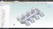
You see, another Parametric CAD rule that I didn't talk about in our call is this: If at all possible, leave you fillets and chamfers for the absolute end. The reason your shell was failing is that you filleted between the plenum and the runners before the shell.

Parametric CAD software are very clever when they are not very dump. This is an example to the latter. By shelling for the offset you wanted some of the surfaces created by the fillets will be shrunk out of existence. And Shell will not do anything if it cannot do everything. That is create an equivalent surface out of every surface you do not want to delete. So, if you shell before the fillets and add them later you have significantly better chances to get the shell going.

But all in all, miles better design process than your earlier attempt.

P.S. I know you don't need the top cut off like that. I just did it so you can better see inside.
 

Attachments

  • From kcoffield.AD_PRT
    6.6 MB · Views: 2
Last edited:

kcoffield

Member
Kelly, you're actually there. You did it. That will work. I was pretty sure it would but I wanted to try it first.

Wow! Thank you Konstantinos. I won't be able to look at it until a little later on but that shelled model is a thing of beauty to see.

You see, another Parametric CAD rule that I didn't talk about in our call is this: If at all possible, leave you fillets and chamfers for the absolute end. The reason your shell was failing is that you filleted between the plenum and the runners before the shell

Man, I had that all wrong. I thought somewhere along the line it was suggested things were more likely to shell with fillets. In the future I'll remember to try shelling before adding fillets.

P.S. I know you don't need the top cut off like that. I just did it so you can better see inside

Actually the top does come off and there is a seperate part that bolts on the top to adapt to the carburetor. There are several interchangeable versions of this carb adapter (top) and it also allows internal access to plenum for "hand porting". I need to add a few small bosses for mounting and machining/work holding aids but I didn't want to clutter up the model with the small detailed features.

But all in all, miles better design process than your earlier attempt

I have a ridiculous amount of time into this model, but the majority of that is really more learning Alibre than modeling......and there sure was a lot of learning. The required features and position of the "Runners" are really the challenge. I think I actually have five different modeling methods for those runners; just extrusions/extrude cuts, just a sweep, combination of a sweep and extrusions/cuts (the successful model), several versions that use lofts.

There was way too much learning for me to list here, but in general, I had better luck using a larger number of sketches with simpler geometry to create the solids, use patterns and mirror where possible, to achieve the final shape. It made getting the sketches fully defined easier, and allowed more opportunity to discover where problematic geometry was created or avoided.

Best,
Kelly
 

Ex Machina

Senior Member
...
There was way too much learning for me to list here, but in general, I had better luck using a larger number of sketches with simpler geometry to create the solids, use patterns and mirror where possible, to achieve the final shape. It made getting the sketches fully defined easier, and allowed more opportunity to discover where problematic geometry was created or avoided.

Best,
Kelly
I think you said it all in that last paragraph. More sketches but simpler is a great way to go. That's what I always try to go for if possible. But I think you're picking it up quite quickly. Good job.
 

Ex Machina

Senior Member
Not quite. Not my kind of music, and Geez I had almost gotten them out of my mind. :rolleyes:
Check the link.
I did. It was a joke. Not a good one apparently... Sorry.

But yeah, "Keep it Simple, Stupid" is probably the best advice I have ever gotten. I also had a teacher who said, if you can't make a simple design to meet the specs, you need to work more on the basics (of engineering).

Good advice.
 

HaroldL

Alibre Super User
I did. It was a joke. Not a good one apparently... Sorry.
Hey, no problem, I go it.

About your Leader Board Challenge video though, great video. It really shows the power of using shortcut keys.
You should do a video discussing how you set up your Shortcut Keys in Alibre. I have a few of them but haven't taken the time to do a "complete" list.
I am reminded of the 2D CAD program we had at work, I-DEAS Master Drafting. It had either a one or two letter key for every command and option on the menu. I got to the point that I could produce a complete 2D drawing just by hitting the right shortcut keys. They were all predefined so the users couldn't set their own, which made it nice if you had to use a different workstation from time to time.
 

Ex Machina

Senior Member
Hey, no problem, I go it.

About your Leader Board Challenge video though, great video. It really shows the power of using shortcut keys.
You should do a video discussing how you set up your Shortcut Keys in Alibre. I have a few of them but haven't taken the time to do a "complete" list.
I am reminded of the 2D CAD program we had at work, I-DEAS Master Drafting. It had either a one or two letter key for every command and option on the menu. I got to the point that I could produce a complete 2D drawing just by hitting the right shortcut keys. They were all predefined so the users couldn't set their own, which made it nice if you had to use a different workstation from time to time.
Hey Harold, yeah exactly. It shows what good preparation can do, and setting up hotkeys is part of that good preparation. My next video, that will drop either tomorrow or Thursday, will be about my setup in Alibre and any special tricks used in that video. I will even reveal a special trick I found for Alibre that I didn't use in that challenge video.

But it could come handy in a competition setting. My goal is to have people crowd the top places in the leaderboard and the championships with Alibre, even if I'm not the fastest then.
 

kcoffield

Member
I added some of the addtional detail features and surfaces necessary to generate the CAM program, and ran a quick simulation. Looks pretty good and 45 minutes run time is not too bad considering I made no effort whatsoever to optimize and a piece this size (24"L x 12"W x 3"T). I have a few more tweeks to make to the model and still some addiitonal work to do since there is a program required for machining each side of each half, but looks like I'm ready to move from design phase to making the pattern and casting.

Spider Ready for CAM CNC.jpgSpider Test Cut.jpg

Best,
Kelly
 
Last edited:

Ex Machina

Senior Member
That is Amazing, Kelly!!! Just for the laughs, flip back a couple of pages in this thread to see how this started!

Great job! Well Done!!!
 
Top