What's new

How do I align a tube to a spoked wheel?

Thompson

Member
I tweaked your model a little using an approach you may want to try:
I modded the spoke with a flat spot near the hub end. It's labeled "location feature" in the design tree.
I modded the pulley with a cylindrical feature on the inner edge of the front face - "location features 1a & 1b".
The flat spot and cylindrical face were connected with a tangent mate.
Done!
No matter how many spokes are made or what angle they are at, the first spoke will always center itself and slide against the location feature 1b "pin". The sketch for "location feature 1a" has an angle dimension that can be adjusted so that the spokes line up with the hooks properly (I forgot to adjust it before I uploaded the file... oops)
If you put a very tiny part-of-a-circle "belt" cut on the inside curved part of the J hook, those can be made to snuggle up to the spokes properly, too.
I do stuff like this all the time in Solidworks at work. Normally after getting things mated up I would make the location features very, very tiny so they wouldn't be visible in any drawing - it also reduces any dimensional discrepancies to harmless levels. I left them pretty big here to be easy to find.
 

Attachments

  • L-Bracket to Sidewall Cheoy Lee Clipper 48 demo.AD_PKG
    2.3 MB · Views: 4

idslk

Alibre Super User
Hello @Thompson ,

if you switch the configuration from 12" to 9" of the pulley, you get this:

upload_2020-1-5_10-36-46.png

In addition you have no automatic positioning of the pulley to the the j-hooks. They are the "positioning element" for the spokes...

Regards
Stefan
 

Thompson

Member
Hello @Thompson ,

if you switch the configuration from 12" to 9" of the pulley, you get this:

View attachment 29359

In addition you have no automatic positioning of the pulley to the the j-hooks. They are the "positioning element" for the spokes...

Regards
Stefan

Yes, I see! It was just a quick hack to show the principle only and I didn't check the 9" configuration. As is, when switched to the 9" configuration, location feature 1b breaks loose and is no longer in the correct spot. Constraining the location features so that they stay in their proper positions in different configurations is just part of building the model properly and beyond the scope of the hack (it was late & I was lazy).

I suppressed the J hooks because I didn't want to take the time to modify them also. The same hack would position them against the spokes vertically, and changing the sketch for location feature 1a so that the cut was located a certain distance from the hook hole instead of an angular amount would give proper positioning in all configurations. (the hook holes throw an error in the 9" configuration, anyway - a moment of schadenfreude here!)
 

idslk

Alibre Super User
Hello @Thompson ,
i don't know which model your refering to, but what kind of error do you get from the 9" config hook holes?
If you take a look at the package from post #18, you will see that no additonal tiny parts or changes on the original parts are neccessary to get the model constraint. I tried it without any changes because if it is a "steering wheel" on a ship, i'm not sure if anybody wants to get this thing changed or possibly damaged...
Beside that, @eron asked about to get his model be constraint, not redesigned...:)
Regards
Stefan
 

Thompson

Member
Hello @Thompson ,
i don't know which model your refering to, but what kind of error do you get from the 9" config hook holes?
If you take a look at the package from post #18, you will see that no additonal tiny parts or changes on the original parts are neccessary to get the model constraint. I tried it without any changes because if it is a "steering wheel" on a ship, i'm not sure if anybody wants to get this thing changed or possibly damaged...
Beside that, @eron asked about to get his model be constraint, not redesigned...:)
Regards
Stefan

Well, on the Wheel Adaptor 12 part, changing to the 9" configuration causes the J-Bolt Holes feature to break with:
"Plane no longer available:com.alibre.design.ops.OperationTargetProxy topologyAutographOrGuid = #6"

As far as your next comment is concerned, I'm not sure what point you're trying to make. There are numerous ways to the same end. The more solutions someone is exposed to, the better.Your solution is just fine. Kudos.

There are pros and cons to any method. Each should be evaluated for its utility in the given situation. For example, if the model is exported as a step file any constraints AND reference points and axes disappear. I have found that reconstituting a working model from one that extensively used reference geometry elements to hold things together is considerably more tedious than from one that only used geometric constraints. Interoperability may be something that I am much more concerned about than you are. My models often have to move back and forth between Alibre and Solidworks, so I tend to try to avoid reference geometry when I can.

Sigh... the OP said he was looking for a solution to his problem and did not specify the required nature of that solution. Nothing was "redesigned". I'm glad you are concerned about boaters' safety - so am I. I haven't killed anyone yet.;)
 

GIOV

Alibre Super User
No, No, as Naval Architect I am very disappointing in these solution. It's so unsafe when you are sailing. The steering must have appropriate pedestal, so take a look and happy new sailing year 2020! (If I have little time I will check the eron drawing).
upload_2020-1-5_18-21-2.png
chain_wire_steering.jpg

upload_2020-1-5_18-23-0.png
https://www.bwsailing.com/cc/2017/03/what-to-do-when-your-steering-fails/
 
Last edited:

GIOV

Alibre Super User
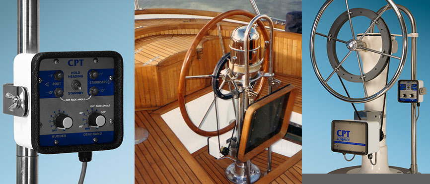
If it 's autopilot, normally are installed as auxiliary in the boat pedestal. I don't have experience in this device.
cpt_photos.jpg
 
Last edited:

eron

Member
I tweaked your model a little using an approach you may want to try:
I modded the spoke with a flat spot near the hub end. It's labeled "location feature" in the design tree.
I modded the pulley with a cylindrical feature on the inner edge of the front face - "location features 1a & 1b".
The flat spot and cylindrical face were connected with a tangent mate.
Done!
No matter how many spokes are made or what angle they are at, the first spoke will always center itself and slide against the location feature 1b "pin". The sketch for "location feature 1a" has an angle dimension that can be adjusted so that the spokes line up with the hooks properly (I forgot to adjust it before I uploaded the file... oops)
If you put a very tiny part-of-a-circle "belt" cut on the inside curved part of the J hook, those can be made to snuggle up to the spokes properly, too.
I do stuff like this all the time in Solidworks at work. Normally after getting things mated up I would make the location features very, very tiny so they wouldn't be visible in any drawing - it also reduces any dimensional discrepancies to harmless levels. I left them pretty big here to be easy to find.

Thompson, I really like this approach, it is simple and adaptable. I was hung up on forcing the modeled parts to constrain together as they are and did not consider adding some features just to make the constraints work. Thank you!

angled spoke constraint thompson solution.png
 

eron

Member
Here are photos of the actual wheel the pulley will install to. The boat is Cheoy Lee Clipper 48. The system is an auxiliary wheel mounted autopilot. The wheel is driven at about 6 RPM.

helm1.jpg helm2.jpg
 

eron

Member
Hello colleagues,

i've added more planes, an axis and an point and now it works without any offset in constraints (and of course without calculations...)
Have fun!

Regards
Stefan

Thank you Stefan, I see that you mated a point on the pulley to a plane on the spokes and did this with two spokes to completely constrain the parts. It does work well, even when the spokes or pulley are changed. I didn't realize you could constrain to a point. This has all been very helpful!

Eron
 

idslk

Alibre Super User
Hello eron,

thank you for the pictures and nice to see you got a solution.
Can you post the result package?
Thank you in advance.

Regards
Stefan
 

GIOV

Alibre Super User
thank you for your additional information.
Stefan: You are welcome.
I advice to replace the original steering wheel by other with flat spokes. It will be more robust installation. The autopilot engine box must be installed in the pedestal as "one assemble".
 
Last edited:
Top