What's new

Using Master Sketches in Assemblies

I'm still pretty new to Alibre Design. How do I create a master sketch that can be used as the main/only reference for several parts in an assembly? I've been trying to figure out the best practices for using inter design relationships with mixed results. I figured having one reference for everything would be more reliable than having each part reference the part before it.

If this is not possible, what are some of the best practices for using inter design relationships? I haven't been able to find much info on here other than "don't use them", which seems like a missed opportunity given how useful they are. Especially since using master sketches and reference geometry are key workflows in both Fusion360 and FreeCAD. Thanks for your help.
 

dwc

Alibre Super User
Hi Generic,
A sketch is the basis for a part. An assembly is several parts. As such there are no assembly sketches.
When I need such a master sketch I have two strategies as I have recently described in another thread.
1) make a part out of your master sketch, say 1mm thick. You can then use that to project the edges you need to your specific parts.
2) make a master sketch with all the lines for all your parts and us that same sketch in all your parts. Change the lines you don't need for a specific part to reference lines.
For the rare times I have needed a master sketch these have worked well for me. I hope for you too.
In AD there are almost always several ways to solve any problem. They may just not be the ways other programs may prefer.
Don
 
Thanks for the reply. The reason I don't/couldn't extrude the reference sketch was because it's not a valid sketch.

How do you copy the sketch from one part to another while maintaining it's positioning? If you have to change something in the master sketch I assume you have to change every copy of the sketch individually, right?
 

albie0803

Alibre Super User
Open a new sketch, select Project to Sketch, select your master Sketch, select Maintain association to source identity.

Now if you edit your master sketch, any sketches associated in this way will update to match it.
 

MilesH

Alibre Super User
How do you copy the sketch from one part to another while maintaining it's positioning? If you have to change something in the master sketch I assume you have to change every copy of the sketch individually, right?
You only have access to solid geometry between Parts.
 

NateLiquidGravity

Alibre Super User
Open a new sketch, select Project to Sketch, select your master Sketch, select Maintain association to source identity.

Now if you edit your master sketch, any sketches associated in this way will update to match it.
The following changes to the original sketch do transfer:
Length/size changes of sketch existing objects.
Position changes of sketch existing objects.

The following changes to the original sketch don't transfer:
Adding new sketch objects.
Deleting sketch objects.
Shape patterns.
Text.
Other things I haven't tried?

But I also experience things projected to sketches with maintain association sometimes still not maintaining association. I was fighting that this week in addition/association to the resulting interdesign constraints breaking assembly constraints. There is fixing that Alibre needs to do there yet.
 

MilesH

Alibre Super User
That's all fine, or not, for transferring between Sketches within a Part. What Generic0000 wants to do, as I understand it, is to transfer Sketches between Parts. Yes, you can transfer Sketches between Parts and maintain the original positioning using "Copy/Paste with Base Point" but there's no way to maintain Associativity. Even if we had Reference Geometry Inserted into a Sketch which was accessible from another Part that would be a start. All we have is Solid Geometry though. Sure, you can make Ghost Parts with minimal opacity, or hide them when they're not being referenced but.... Anyway, there's no 'master Sketch' in Assembly and no real 'master Sketch' within a Part, controlling other Parts in an Assembly, either.
 
Last edited:
Thanks for a all the responses. Yes, I was asking about making a sketch that could be referenced by multiple parts and would push down any changes to dependent parts. It seems that is not possible in alibre.

Since I can't create one sketch that everything else is referenced to, what are some best practices for using inter design relationships? Obviously, make relationships only one way, for example.

I'm self taught with CAD and I think I design top down most of the time.

My last project had a relationship brake and I didn't know it until it was being printed. That's what sent me down the rabbit hole of trying to make more robust relationships.

I'm new to alibre, but have been using FreeCAD at work for years and I've dabbled in fusion off and on too. Thanks again for all your help.
 

dwc

Alibre Super User
To clear that up.. I don't transfer the sketch from one part to the next.
I have the sketch in a part that I save under many names.
Then I edit those parts as needed.
The disadvantage, you can not change the master sketch and have it propagate to the others.
 
Last edited:
To clear that up.. I don't transfer the sketch from one part to the next.
I have the sketch in a part that I save under many names.
Then I edit those parts as needed.
The disadvantage, you can not change the master sketch and have it propagate to the others.
Oh..... That makes sense. Do you keep using "save as" and then add them all to an assembly? I'm still trying to wrap my head around Alibre's file management (and don't get me started asking about version management).
 

dwc

Alibre Super User
Oh..... That makes sense. Do you keep using "save as" and then add them all to an assembly? I'm still trying to wrap my head around Alibre's file management (and don't get me started asking about version management).
Yes, as they have different names and were saved using "save as" they are different unrelated parts for AD.
Just be sure you don't use Windows to copy them.
If you do that they will have different names, but are the same part for AD as they have the same internal signature. That will mess everything up.
 

jfleming

Alibre Super User
There is one way that might work for you. Use Global Parameters. Create your GP file with all dimension values to be utilized in the Master Sketch. Create your first part using that sketch. Do a Save As, and save your second part. Both parts would then refer to and utilize the GP values. When you update the GP values, both parts would update accordingly, since the sketch geometry is based off of the GP values.
 
There is one way that might work for you. Use Global Parameters. Create your GP file with all dimension values to be utilized in the Master Sketch. Create your first part using that sketch. Do a Save As, and save your second part. Both parts would then refer to and utilize the GP values. When you update the GP values, both parts would update accordingly, since the sketch geometry is based off of the GP values.

That could work. If I'm understanding you I need to:

1) make a master sketch with all dimensions based on global variables.
2) save that as the different parts I will need (base, lid, ...).
3) do what albie0803 suggested and use a projection of the copied master sketch wherever needed, since each part will have it's own copy.

If all that was done in one assembly, would any changes to the global variables propagate to all copies of the master sketch?

If that works, that could be the solution I'm looking for (and had given up on). I'll have to try it at work tomorrow. It's a bummer this only works for AD expert, since it relies on global variables. I was considering getting Atom for home.
 

simonb65

Alibre Super User
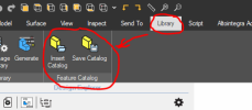
If you have "interfaces" on multiple parts that are something you will re-use over and over, take a look at the Feature Catalog. I use this all the time for flange fittings and electrical panel cut-outs. May or may not do what you need, but it's a very useful tool and often gets overlooked!

1691662771648.png
 
Have you see this video about global parameters?
Yes, thanks. I saw that when I designed a large complicated box of of laser cut acrylic. All the tabs, overall dimensions, kerf,... we're driven by global parameters.
If you have "interfaces" on multiple parts that are something you will re-use over and over, take a look at the Feature Catalog. I use this all the time for flange fittings and electrical panel cut-outs. May or may not do what you need, but it's a very useful tool and often gets overlooked!

View attachment 39381
I'll play around with that. Most of what I do is a one off. But I do see the utility in that.
 

Oldbelt

Alibre Super User
GENERIC000
As I understand you have a box with a lid, if you change the size of the box you want the lid to follow.??
Why not just change those few dims instead of all those fancy ideas at lot of nice people use time to think up.
In that time this post fort and back have taken you could have made a lot of simple dim. changes.
I understand what you are saying, but 1) I'm not just making a box with a lid (that was an example, and that example included "..." meaning more parts), and 2) I'm trying to figure this out for when I have a more complicated design (I'm still trying to learn Alibre Design after using FreeCAD for many years). Also, it doesn't take much complexity for changing everything manually to become hugely cumbersome and increases the chances of missing a dimension.


Do a Save As, and save your second part. Both parts would then refer to and utilize the GP values. When you update the GP values, both parts would update accordingly, since the sketch geometry is based off of the GP values.
I just tried this with unexpected results. How do you make multiple copies that are in the same place in X,Y, and Z? I tried saving as, and it just renamed the part. I then inserted the old part, but then they are at different locations. I'm still trying to figure out the way files are handled within Alibre (I still think its crazy that you cannot rename a part other than using "save as" which then fills up your project file with unneeded redundant files).
 
Top