What's new

Watching and Performing Actions on Bolts!

silver2row

Senior Member
Hello,

As some of you may know, I am new to the idea of drawing mechanical instances. I have been following along in videos and learning Alibre Atom3D (my current subscription) by way of tutorials recently to learn more.

So, in the bolt video, https://www.alibre.com/atom3d-training/ , I see there is not a set of threads...

Has anyone mastered this portion of the builds without resorting to https://www.traceparts.com/en or another building appliance from different sites online.

I watched the video. I will perform the actions soon. If anyone knows of some steps to take to create threaded components, I would be most pleased!

Seth

P.S. Thank you for your consideration...
 

HaroldL

Alibre Super User
Is this outdated?
No, it explains the basis of creating a helical cut feature.
If you change the circle to a triangle and set the pitch to that of the screw you want to create then you'll have a threaded feature. Although there will necessarily need to be some tweaking of the parameters to fully define the thread.
The crib sheet that Joseph used and demoed in his Quick and Easy video was something I put in the Resources some time ago to help users define the threads they were creating. @Ex Machina takes it to another level with the equation editor. Either method will get you a threaded feature.
 

Stu3d

Senior Member
@Stu3d ,

You rule! Thank you so much.

Seth
Glad I could point you in the right direction but it's the contributors who produce the videos that rule, I am a 2d architect of decades who has only relatively recently stepped in to the 3rd dimension. I used Generic Cadd 3d in the 80's but only for some presentation, now we have 3d printers the skys the limit :cool:
I guess you may be familiar with these but I will list some Youtube places of interest in case others read this who are new to Alibre.

The obvious https://www.youtube.com/@AlibreLLC/videos

Joseph who now produces stuff for Alibre above https://www.youtube.com/@JokoEngineeringhelp/videos

Ex Machina who is the new kid on the block, very knowledgeable and some great tips in the videos https://www.youtube.com/@ExMachinaEngineering

These next two produce very creative video answers to peoples questions here on the forum.
Ken226, path pattern in Atom video particularly useful https://www.youtube.com/@kensmith174/videos
HaroldL, mainly sheet metal but patterned holes on curved surface useful for Atom https://www.youtube.com/@HaroldL-bn4eo/videos

Sorry if I missed anyone and for being off topic but I can't take credit for just watching too much Alibre on Youtube!
 

silver2row

Senior Member
No, it explains the basis of creating a helical cut feature.
If you change the circle to a triangle and set the pitch to that of the screw you want to create then you'll have a threaded feature. Although there will necessarily need to be some tweaking of the parameters to fully define the thread.
The crib sheet that Joseph used and demoed in his Quick and Easy video was something I put in the Resources some time ago to help users define the threads they were creating. @Ex Machina takes it to another level with the equation editor. Either method will get you a threaded feature.
Thank you.

I am learning now all I can. So, if because of the Atom3D source instead of Professional source being in my hard drive, I will attempt what is available with Atom3D accessibility.

Seth

P.S. Yeppers.
 

silver2row

Senior Member
Glad I could point you in the right direction but it's the contributors who produce the videos that rule, I am a 2d architect of decades who has only relatively recently stepped in to the 3rd dimension. I used Generic Cadd 3d in the 80's but only for some presentation, now we have 3d printers the skys the limit :cool:
I guess you may be familiar with these but I will list some Youtube places of interest in case others read this who are new to Alibre.

The obvious https://www.youtube.com/@AlibreLLC/videos

Joseph who now produces stuff for Alibre above https://www.youtube.com/@JokoEngineeringhelp/videos

Ex Machina who is the new kid on the block, very knowledgeable and some great tips in the videos https://www.youtube.com/@ExMachinaEngineering

These next two produce very creative video answers to peoples questions here on the forum.
Ken226, path pattern in Atom video particularly useful https://www.youtube.com/@kensmith174/videos
HaroldL, mainly sheet metal but patterned holes on curved surface useful for Atom https://www.youtube.com/@HaroldL-bn4eo/videos

Sorry if I missed anyone and for being off topic but I can't take credit for just watching too much Alibre on Youtube!
Thank you @Stu3d .

Seth

P.S. I will be reviewing the videos in time. I appreciate you taking time out to assist me.
 

silver2row

Senior Member
Okay Fellows,

It seems I am gaining momentum and new failures so far...

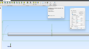
Errors_Galore_2024_01.png

...

I created the triangle. On Alibre Atom3D, can I use construction references? I noticed in the video,
, there is a triangle and the fellow says something about construction reference lines.

I do not know what he is describing. Anyway, That is as far as I can get now. The triangle can be closer but where should its placement be currently?

When I put the triangle on the "bolt," I receive errors relating looping and not closed.

Seth
 

silver2row

Senior Member
I have an update...

So, I am not sure if this is a bug or my computer not playing well with Alibre.

I get a circle not allowing for the processor to achieve its directed command:

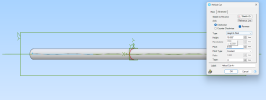
Halting_and_Producing_0_500_pitch.png
 

HaroldL

Alibre Super User
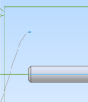
In your previously posted image it appears that you have the sketch located too far from the cylinder to create the helical cut you want.
1705778180235.png

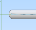
You need to locate the cutting sketch so it is aligned within the body of the cylinder as Joseph shows. Review his video again and see how he has the sketch aligned at the surface of the part. You can select the chamfer and project its edges into your sketch as reference geometry. Then use the end nodes of the projected geometry to constrain the profile sketch to. Use the axis for the axis of rotation for the helical cut.

In your second image it appears the profile sketch is inside the part you want to cut.
1705778526851.png
 

DavidJ

Administrator
Staff member
Imagine the sketch profile as a single point cutting tool on a lathe, that will cut the thread. It has to be positioned to cut the correct depth into the cylinder.
 

silver2row

Senior Member
Everything seems to be working now. I am not sure why earlier the `circle of death` kept spinning while the process was running to create the threads.

Seth

P.S. I have a set of conformed testing steps that create the helical blue lines but nothing else so far. I know what you guys are describing. I need to apply the right sized triangle at the correct location.

# Update

The location is wrong b/c of my 1" * 1" grid and my bolt(s) are 3/8" to 1/2" in diameter.

I will attempt to update the grid to something smaller.
 

silver2row

Senior Member
You got it! That is a superb idea. I was trying to calculate the 1" * 1" area or change that to another area of grid operations. I am wrong in this context.

Although changing the grid does display differently mentally, it really is just getting in my way physically. Thank you again!

Seth
 

silver2row

Senior Member
You might try just turning the grid off and using dimensions and constraints to control your sketch.
I quit using the grid a long time ago, it just gets in my way when working on sketches that have diagonal entities.
@HaroldL ,

Seth here. I am still having a difficult time from the time I click okay/apply in the helical cut tool for carving out parts for threads. I am currently understanding things correctly. This is not the issue.

I am going to read about how to create a triangle of a specific size and shape along with how to create the constraints and dimensions.

...

It seems like when I perform the same actions on specific builds, that is taking the same steps, I get different results. One result is the helical cut tool not allowing an Okay from the user.

I think it is because of the shape and placement of the triangle being used in this light.

Also...

1. For some reason I could not turn off the grid in sketching. I attempted to turn off the button available under sketching in the System Options but notta.
2. Off to try more.
3. I will rewatch the quick video on placing a threaded component on a circular tab base with the extrusions.

Seth

P.S. I am getting the language down slowly so I can interpret what you are telling me and when you tell me. And also, I am trying to slowly get the functioning down pat so I can relay ideas into typing a bit better. Blah. Sorry.
 

silver2row

Senior Member
Design Summary for Threaded_Part

Material = Aluminum, 2024-T3
Density = 2.77 ×10³ kg / m³

Volume = 2.23940465 ×10⁴ mm³
Mass = .062 kg
Surface Area = 7.8255566 ×10³ mm²

Center of Mass
[ 89.0873 mm, 4.3712 ×10⁻⁵ mm, 1.2579 ×10⁻⁴ mm ]

Mass Moments of Inertia
xx: 1.2445 mm²kg
yy: 6.552398 ×10² mm²kg
zz: 6.552398 ×10² mm²kg
yz: 1.2165 ×10⁻⁵ mm²kg
zx: 3.1786 ×10⁻⁴ mm²kg
xy: -1.7713 ×10⁻⁴ mm²kg

Moments of Inertia and Principal Axes
1.2445 mm²kg {1, -2.5896 ×10⁻⁶, -2.3337 ×10⁻⁶}
1.629235 ×10² mm²kg {1.5559 ×10⁻⁶, .9306, -.366}
1.629235 ×10² mm²kg {3.1195 ×10⁻⁶, .366, .9306}

Geometry Summary
Parts : 1
Faces : 8
Edges : 12
Vertices : 9
Unique parts : 1

# That info is from my odd bolt! I got it done finally. Odd...yes. Usable...no. Dang it.

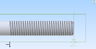
Anyway, please view the photo and reply with any remarks available. I am still trying to make a triangle at the correct section. Obviously, the fellow that made the video is light years ahead of me...

Photo:

First_Bolt_action_.png

Thank you for any pointers you can give. I will keep trying.

Seth
 

HaroldL

Alibre Super User
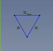
Looks like your getting closer to your goal. The profile sketch in your image appears to be a right triangle, it should be an quadrilateral triangle. Edit the sketch and remove any vertical constraint, and apply an Equal constraint to all line segments. That is step one in getting the thread form for the helical cut. Dimension its position from the axis or origin to the horizontal line to be equal to the radius of the part.

1705823858493.png

. For some reason I could not turn off the grid in sketching.
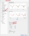
Turn the grid and grid snapping off in the System Options

grip off.jpg


P.S. I am getting the language down slowly so I can interpret what you are telling me and when you tell me.
Learning the language of CAD can be almost as challenging as learning the program, but as the saying goes "Practice make perfect", or at least close to it.
 

DavidJ

Administrator
Staff member
For some reason I could not turn off the grid in sketching. I attempted to turn off the button available under sketching in the System Options but notta.

There are 2 settings, one for sketch in parts - the other for sketch on 2D drawings.
 

silver2row

Senior Member
Looks like your getting closer to your goal. The profile sketch in your image appears to be a right triangle, it should be an quadrilateral triangle. Edit the sketch and remove any vertical constraint, and apply an Equal constraint to all line segments. That is step one in getting the thread form for the helical cut. Dimension its position from the axis or origin to the horizontal line to be equal to the radius of the part.

View attachment 40679


Turn the grid and grid snapping off in the System Options

View attachment 40680


Learning the language of CAD can be almost as challenging as learning the program, but as the saying goes "Practice make perfect", or at least close to it.


Hello...yes. I understand the grid options in the System Options. I clicked the buttons off and I still have the grid in the 2D Drawings. I read what differences are listed in the sketching and 3D non-sketching options.

No issue either way. I will attempt to make the triangle a quadrilateral triangle with the Equal Constraints. Thank you again.

Seth

P.S. Just for reference, I never had any grid in the 3D non-sketching portion of the source.
 
Top