You are using an out of date browser. It may not display this or other websites correctly.
You should upgrade or use an alternative browser.
You should upgrade or use an alternative browser.
Watching and Performing Actions on Bolts!
- Thread starter silver2row
- Start date
Hello Seth,
The earlier sketch looks like your thread included angle is 90 degrees.
The printed 3D model looks the same.
Most threads are 55 or 60 degrees inclusive. Imperial = 55 degrees. & Metric 60 degrees.
If you change your sketch to a 55 or 60 degrees it WILL go deeper.
Hope this helps.
Jim
The earlier sketch looks like your thread included angle is 90 degrees.
The printed 3D model looks the same.
Most threads are 55 or 60 degrees inclusive. Imperial = 55 degrees. & Metric 60 degrees.
If you change your sketch to a 55 or 60 degrees it WILL go deeper.
Hope this helps.
Jim
silver2row
Senior Member
@JimCad ,
Yeppers sir, it seems my threads are a "bit" or a lot overstated or understated with my current builds. When I use the Line Tool and Equal Constraint Tool, I am not getting degrees.
The first triangles were 90 degree angled triangles. Boo to that idea. I know now! Anyway, I will work on 55 and 60 degree angles for my angles of the quadrilateral triangles.
Seth
P.S. Thank you for pointing this out. For now, I am purely working on regular threaded, coarse threads and fine threads, of bolts for a build I will make one day on a lathe (hopefully). The 3D printing is for testing purposes, i.e. it is way more inexpensive to 3D print a piece with $0.075 of filament compared to ruining a good stock of rebar or other type of testing stock that is metal.
silver2row
Senior Member
Okay,
So, with building the triangle and exchanging out formatted degrees and equality, I have an other question here:
1. What is this pop up?
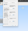
2. Are those values regular for an export to .stl format?
3. I do not mind the export but would rather understand more about what these options mean in reference to:
a. Normal Deviation
b. Surface Deviation
c. Maximum Cell Size
Seth
P.S. I see the photos and the small explanation but in a more general context, how should I interpret these options? Is the normal deviation what I should create to 60 degrees? With the facet, is this the external protrusion of excess outside of a core? Then, the length of the surface deviation would be some numerical value of maximum extruded outer portions of the core? I am guessing so far.
So, with building the triangle and exchanging out formatted degrees and equality, I have an other question here:
1. What is this pop up?

2. Are those values regular for an export to .stl format?
3. I do not mind the export but would rather understand more about what these options mean in reference to:
a. Normal Deviation
b. Surface Deviation
c. Maximum Cell Size
Seth
P.S. I see the photos and the small explanation but in a more general context, how should I interpret these options? Is the normal deviation what I should create to 60 degrees? With the facet, is this the external protrusion of excess outside of a core? Then, the length of the surface deviation would be some numerical value of maximum extruded outer portions of the core? I am guessing so far.
Stu3d
Senior Member
Normal deviation controls how many faces your curved object has. Lower the number the smoother the model, I usually use 3 degrees or 2 degrees for larger objects. Set it at 90 degrees, view exported STL of the bolt and you will see what I mean.
I have always left the other 2 boxes unticked.
I have always left the other 2 boxes unticked.
Click on the question mark at bottom right of the dialogue - that will take you directly to the related Help section.
 help.alibre.com
The default settings are usually a good place to start and will work well for the majority of models. Sooner or later, you'll have a model which needs you to change the settings to get a good result. This is usually compromise between print smoothness and STL file size.
Articles
The default settings are usually a good place to start and will work well for the majority of models. Sooner or later, you'll have a model which needs you to change the settings to get a good result. This is usually compromise between print smoothness and STL file size.
silver2row
Senior Member
Thank you Fellows,
I appreciate you guys replying so quickly. I see the question mark now. Thank you.
Seth
I appreciate you guys replying so quickly. I see the question mark now. Thank you.
Seth
silver2row
Senior Member
I am not sure how affective my check marks or the lack there of a check in this dept. makes but...
1. I have another print to show off.
2. I will keep testing to get better acquainted with the source and print outcomes.
Photo:
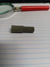
There are obvious issues and problems here, i.e. outside of me blabbing too often already.
The bolt. It is quite awkward. 25mm of threads while the entire bolt is 40mm. The Pitch is a big failure too: 2.0 is the Pitch which is 12.7 threads per inch.
It is funny that the 2.0 mm pitch is available since I am using a 0.5mm for XY spacing on the grid for Sketching. Wait, I am not. I have the grid...dang it.
Okay, so. The grid is there and shown as viewable and usable but my button is unclicked and my grid for XY both equal 0.5mm for grid spacing. The grid is not spaced at 0.5mm * 0.5mm.
I probably clicked the change in the middle of the build. This is why I am seeing 0.5mm * 0.5mm as not working for the grid even though the grid is available.
Seth
P.S. Odd bolts and lacking mathematical representation here! What is the deal with 1.27 cm in regards to the Exercise Manual which is found here: https://www.alibre.com/AlibreDownloads/Manuals/Atom3D_ExerciseManual_v24.pdf . Anyway, nosy me and my excessive questions. I know...
1. I have another print to show off.
2. I will keep testing to get better acquainted with the source and print outcomes.
Photo:

There are obvious issues and problems here, i.e. outside of me blabbing too often already.
The bolt. It is quite awkward. 25mm of threads while the entire bolt is 40mm. The Pitch is a big failure too: 2.0 is the Pitch which is 12.7 threads per inch.
It is funny that the 2.0 mm pitch is available since I am using a 0.5mm for XY spacing on the grid for Sketching. Wait, I am not. I have the grid...dang it.
Okay, so. The grid is there and shown as viewable and usable but my button is unclicked and my grid for XY both equal 0.5mm for grid spacing. The grid is not spaced at 0.5mm * 0.5mm.
I probably clicked the change in the middle of the build. This is why I am seeing 0.5mm * 0.5mm as not working for the grid even though the grid is available.
Seth
P.S. Odd bolts and lacking mathematical representation here! What is the deal with 1.27 cm in regards to the Exercise Manual which is found here: https://www.alibre.com/AlibreDownloads/Manuals/Atom3D_ExerciseManual_v24.pdf . Anyway, nosy me and my excessive questions. I know...
Stu3d
Senior Member
It looks like there are 8 or 10 print layers per 2mm thread suggesting your slicer is set to .2 or .25mm layer height which is too coarse for something with fine detail. Try setting your slicer to 0.1mm layer height. When printing at 0.1mm layer height I increase the first layer to 0.2mm, in my slicer that is done by setting it to 200%.
The threaded part of the print doesn't look like the filament is hot enough as it hasn't fused together well or it is being over cooled by the fan.
1.27cm in that exercise is just a 1/2" grid converted to metric. I think people don't use a grid except in unusual circumstances.
The threaded part of the print doesn't look like the filament is hot enough as it hasn't fused together well or it is being over cooled by the fan.
1.27cm in that exercise is just a 1/2" grid converted to metric. I think people don't use a grid except in unusual circumstances.
silver2row
Senior Member
Okay about the layer height. In CURA, I just have an option to click, i.e. radio button controls the height of layers or I can adjust manually per mm.
I cannot get rid of the grid so far. I unclick the radio button for the grid in System Options but the grid stays put on Sketching 2D when I go to Activate 2D Sketch.
I will keep trying with removing the grid.
I cannot get rid of the grid so far. I unclick the radio button for the grid in System Options but the grid stays put on Sketching 2D when I go to Activate 2D Sketch.
I will keep trying with removing the grid.
silver2row
Senior Member
I found it! Okay, no grid! Myself over here was trying to click and unclick the same items acting like something would change. Blah.
silver2row
Senior Member
It looks like there are 8 or 10 print layers per 2mm thread suggesting your slicer is set to .2 or .25mm layer height which is too coarse for something with fine detail. Try setting your slicer to 0.1mm layer height. When printing at 0.1mm layer height I increase the first layer to 0.2mm, in my slicer that is done by setting it to 200%.
The threaded part of the print doesn't look like the filament is hot enough as it hasn't fused together well or it is being over cooled by the fan.
1.27cm in that exercise is just a 1/2" grid converted to metric. I think people don't use a grid except in unusual circumstances.
Okay...
So. I set the slicer to 0.15mm layer height and a start of coarse height of 0.30mm. I will keep testing with my current bolt since I have a good fix on the "no grid" situation.
Seth
P.S. I am testing with coarse at 0.20mm in one option but it states 0.15mm in my settings. I am probably goofin' up again with the slicer. BBL!
silver2row
Senior Member
One last idea before I move on for a couple hours...
1. Would it be an issue for me to make others understand about Alibre Atom3D and my "successful" ways/attempts without mentioning my pitfalls?
2. For instance, I am more of a layman in Alibre jargon for now and usage is minimal on my part because of past issues that are not an issue any longer...
3. So, I figured starting small here with me at the helm could help a bit.
I am not even sure if I could promote things in a friendly manner enough for others to grasp my simplistic concepts.
For instance, I could run through what was described to me here if that would be okay with others here...
Seth
P.S. I understand that you guys are well far more equipped to handle conversation in Alibre and tutorials galore. I am not discrediting that fact. I am just thinking it may prove valuable for others looking to get into thread making without the higher price of the Thread Options in the higher level purchases of Alibre like Design Expert and so on... No charge. I have always wanted to relay data to others looking into thread making. Although boring to some, it is sort of a step up in my life...
Grass cutting duties abound on my end here! oh! The latest-greatest:
The one on the right is the latest without the grid.
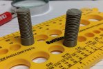
I am still working on the z_hop at the end of the print so swirlies do not take place.
1. Would it be an issue for me to make others understand about Alibre Atom3D and my "successful" ways/attempts without mentioning my pitfalls?
2. For instance, I am more of a layman in Alibre jargon for now and usage is minimal on my part because of past issues that are not an issue any longer...
3. So, I figured starting small here with me at the helm could help a bit.
I am not even sure if I could promote things in a friendly manner enough for others to grasp my simplistic concepts.
For instance, I could run through what was described to me here if that would be okay with others here...
Seth
P.S. I understand that you guys are well far more equipped to handle conversation in Alibre and tutorials galore. I am not discrediting that fact. I am just thinking it may prove valuable for others looking to get into thread making without the higher price of the Thread Options in the higher level purchases of Alibre like Design Expert and so on... No charge. I have always wanted to relay data to others looking into thread making. Although boring to some, it is sort of a step up in my life...
Grass cutting duties abound on my end here! oh! The latest-greatest:
The one on the right is the latest without the grid.

I am still working on the z_hop at the end of the print so swirlies do not take place.
silver2row
Senior Member
@HaroldL ,
I just rewatched the video. Thank you kind sir. I really appreciate you taking time out. Anyway, I have not mastered it yet. In the near future, tis will be!
Seth
P.S. I just noticed a new section to the video about lining things up that brazed by me too quickly the first four times I watched it. I will try to align and constraint for alignment soon. In any light, very much appreciated. First 3D and then to the lathe! Currently, I am working on a stamp bolt. 5/16" threads for about 1/2" to a solid cylinder at 1/2" or a bit more.
This way, I can put my stamp with the threaded bolt at 5/16" as the nut. Then, the 1/2" diameter of the rest of the "bolt" goes into the 200w soldering iron so I can stamp thinks like wood and leather...
silver2row
Senior Member
That is common - just set STL export units in Alibre to mm - then you can design in whatever units you desire, and STLs will always be in mm (at the same physical size).The printer firmware only prints in mm
silver2row
Senior Member
Thank you for the data.That is common - just set STL export units in Alibre to mm - then you can design in whatever units you desire, and STLs will always be in mm (at the same physical size).
Seth
P.S. I will set the export units in Alibre to be mm instead of inches. A while back, while using laser engraving/cutting to perform actions, my bot went overboard. I had the engraving done in inches and the machine ONLY understood mm (metric). Oops. I had to learn quickly... I thought it was me. Well, it was me but the issue was the imperial versus metric measuring on a cartesian plane.

