What's new

Watching and Performing Actions on Bolts!

silver2row

Senior Member
Hello @HaroldL ,

I noticed in the Equal Constraint icon usage, one would need to have two pieces instead of altering just one piece (closed or open). I also saw that the double lines I can use for the Equal Constraint icon does not work for me. For a reason, I understand but I do not know this reason for now.

So far, I have a 40mm * 12mm cylinder with parallelogram for my cutting of the threads. I have been unable to perform an Equal Constraint use from the docs. pages for some reason.

With this parallelogram, I am planning on tuning it into a triangle to make it so the threads cut.

Seth

P.S. Is there some trick I am missing into making a triangle that can be used instead of what I have currently and how would I achieve this idea? I use the line tool for triangle making. When I try to use the Equal Constraint with the two or three line triangle, I get dumbfounded. The change cannot happen. Anyway, thank you for your consideration so far. I appreciate the support.
 

silver2row

Senior Member
Maybe the Equal Constraint tool is not the one to use. I maybe able to use the Coincident Constraint tool instead. I will report back.

Seth
 

HaroldL

Alibre Super User
Here is the Help article about the Equal constraint. It doesn't indicate that it is not available in Atom3d.


And here is a short video that I hope will help you to create the profile sketch and apply the helical cut for the thread form.


silver2row

Senior Member
Thank you again for taking time out. I will keep reading.

Seth

P.S. Sir, I will reply after viewing the video for a total of many times. The issue I have currently is the Axes. I only have two outside of X and Y. So, I have YX and YZ. So, I think this is the issue.
 
Last edited:

silver2row

Senior Member
Okay, you are right and I am wrong. Obviously! Outside of fun time, I found out how the Equal Constraint works in Atom3D. Phew. So, with this knowledge and I have read your latest post, I have been unable to perform a couple things (lack of knowledge on my part). Oh!

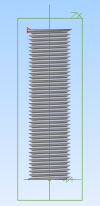
Bolt_One.png

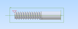
This is with your insight and guidance. I am beside myself. Thank you! The equal constraint works and I am learning about the way you performed the second option in building the triangle for testing purposes.

Seth

P.S. Sir, seriously. Yea boy! It is not perfect yet but I am going to work on it before arriving at a final piece of "working" bolt.
 

silver2row

Senior Member
Oh,

The lack of knowledge on my part I was discussing in my last post...

1. I can bring the Project to Sketch method for the piece (triangle) to the sketch but only if the, from what I am guessing, triangle is not using equal constraints.

Just that one for far.

Seth
 

HaroldL

Alibre Super User
It shouldn't matter if the equal constraint is being used or not. Project to Sketch is a separate function that can be used while creating and/or editing a sketch to add extra sketch figures, regular or reference, to the sketch.
 

silver2row

Senior Member
No issue. I am going to start from scratch on a build and see if I can duplicate my error and move past it. Oh!

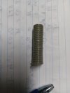
first_bolt.jpg

That is the printed bolt so far.

It is 0.75 in pitch at 12mm * 40mm. I need to alter it a bit and change it.

At first I thought the bolt had a taper but it does not. It is just messed up from me.

Seth

P.S. And okay about the Project to Sketch option... I will try to use it while altering the part instead of going back and forth from 2D sketching to 3D viewing and altering. Thank you again for the input.
 

silver2row

Senior Member
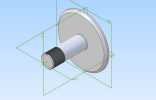
Base_Rod_Thread.png

I am learning slowly. I am sure there are a ton more tricks and ideas to perform. I am trying to get threading down right now.

Seth

P.S. Thank you for assistance and helping me through with ideas and backed up data. Thank you!
 

silver2row

Senior Member
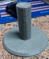
seems.jpg

...

So, this is what I made. Not so much worthy of the time but I am new to the whole thing.

And...

1. I see a seam in the build, i.e. as you can see too.
2. Is this related to the host software, not Alibre Atom3D, or my desktop machine printing incorrectly?
3. Does anyone come across this issue when exporting .stl files with the Alibre Atom3D source?

Do not get me wrong, I am trying to minimize errors in time. I am not blaming here or anyone or Alibre source...

I mean...

a. I checked around my CAD/CAM program instance.
b. I did not see seams or oddity in a build that would come later.
c. So, if this is not wanted on this site, okay.

I will try to minimize in my own time without the community support. Please remember I am minimizing errors in time and trying to track down the root cause before proceeding further.

Sorry if this irks you or anyone...

Seth

P.S. Thank you for the help and for reading me odd pleas. The main reason I bring it up here is that the Equal Constraint tool option allows for building the quadrilateral triangle I need to procure the threads but the leftover piece, that triangle, may be leaving a line where my .stl exported file reads it has an oddity or line of sorts or lines. I am just thinking out loud. If anyone has any insight or suggestions, please reply to me.
 
Last edited:

Stu3d

Senior Member
View attachment 40698

...

So, this is what I made. Not so much worthy of the time but I am new to the whole thing.

And...

1. I see a seam in the build, i.e. as you can see too.
2. Is this related to the host software, not Alibre Atom3D, or my desktop machine printing incorrectly?
3. Does anyone come across this issue when exporting .stl files with the Alibre Atom3D source?
The seam is a result of the 3d printer starting at the same place each layer. Slicing software generally has the settings to make that starting point random or positioned somewhere out of sight, latter not relevant here.
When printing something this detailed the layer height must be small, 0.1mm maximum.
I would not attempt to 3d print a thread this fine.
As a starting point draw a larger bolt with a coarser thread and print that with a small layer height then try smaller threads to find out when it becomes unfeasable.
 

dwc

Alibre Super User
It looks to me like your printer need maintenance.
You can see in the picture that there is a seam in the outer edge of the foot also and there the start and end of the edge do not seem to be at the same place.
It looks to me like you have some slop in the XY plane of your machine that needs to be tightened up.

Making threads on an FDM printer is always a bit touchy.
In general I run the printed parts through the corresponding tap or die to get parts that work better.
 

silver2row

Senior Member
I know. Just call me stitches here. It looks like a horror scene from some scary movie.

Anyway, I will goof with the slicer settings and we are sure this is not an issue with the exported .stl file. Are we sure?

Seth

P.S. Thank you @dwc for your input. @Stu3d , yes. More setting in the slicer... Currently, and I understand that this is not Alibre realm stuff here that is causing the contraption and slicer to not coincide well with one another. Anyway, thank you both for your time and effort. I have lots to do and lots to learn!
 

silver2row

Senior Member
Okay,

Sorry, first off. Secondly, there is an option for `seam`. Odd but true here. So, it is definitely not the Alibre Atom3D and my poor judgment. It is my slicing program which is not covered here by anyone. Okay...understood.

Seth

P.S. It is like I am new to life today!
 

NateLiquidGravity

Alibre Super User
Your threads are so fine (small) that they are getting lost in your layer height. Make them deeper and wider - multiple layers thick if you can. Your STL export settings could have an effect but not that much of one to cause that. The seam is common and called Z Seams or Vertical Seams. https://www.anycubic.com/blogs/3d-printing-guides/3d-print-z-seam Google those terms along with your printer or slicer and you will find lots of suggestions.
 

Stu3d

Senior Member
I have lots to do and lots to learn!
That is what makes hobbies like 3d design, 3d printing, electronics, coding etc. so fun and addictive. It's all about problem solving. I used to go to the library every week, now you can search for anything on the internet and Youtube has so many good tutorials.
I have friends who build those large Lego kits like the Titanic, I would rather design the Lego kit.
If you are new to 3d printing, practice with a calibration cube or benchy to dial in the slicer settings for your printer. If you are not new to 3d printing a new printer or different slicer still takes time to adapt to.
Here is a troubleshooting guide from my preferred slicer Simplify3d, there will be lots more on the internet https://www.simplify3d.com/resources/print-quality-troubleshooting/
Regarding STLs from Alibre I have printed 100s, if not 1000s, and never had an issue. Just make sure you have done Generate to Last Feature before producing an STL or you may miss features below the dog bone.
 

DavidJ

Administrator
Staff member
If in any doubt about the STL file, view it in separate software to check the quality.

Your Slicer is the obvious first choice, I also use the free basic version of Netfabb.

Once in a while you may have a design that will need you to tweak the STL output settings to get good results.
 

silver2row

Senior Member
Okay!

The file is fine, i.e. the exported .stl file is fine. My build for the export is a bit different, e.g. the fine threads at 0.75 mm.

So, I used my source for the slicer to track down the, and get this, SEAM option. It exists! I never changed it or altered it but it was altered and picked! So, I used the radio button to unclick it. Wala.

Done.

Now, onto changing the depth of the threading. How would one go about changing the depth?

1. Larger triangle?
2. Position of the triangle?
3. Something I may never think of currently or another type of understanding I do not currently hold?

Seth

P.S. Off to test! So, with out the quadrilateral triangle, I tested a larger triangle:

Bolt_One_Larger_TPI_Pitch.png

That so far is the outcome...

I can move back to the type of triangle I need to use. Not an issue at all.

Seth

P.S. Thos are larger threads, e.g. less TPI and greater Pitch.
 
Last edited:

silver2row

Senior Member
@HaroldL ,

Hey sir, Seth here. Thank you for your assistance in making me understand things.

For reference only here, I cannot remove the grid in the sketching application part of the software. I tried with the button available in System Options. I am printing my latest-greatest now. Wait for the big, ole threads!

@NateLiquidGravity , thank you for your input. I made the threads a bit larger with less TPI (threads per inch). They are oversized now on the printing application I am applying now.

Seth

P.S. Wait for my photo!
 
Top