You are using an out of date browser. It may not display this or other websites correctly.
You should upgrade or use an alternative browser.
You should upgrade or use an alternative browser.
Working on Threads, Actual Threaded Parts, with Alibre Atom3D and Printing Them!
- Thread starter silver2row
- Start date
silver2row
Senior Member
The new one(s) are better with more life-like threading. Oh and thank you for the support. Much appreciated...
Seth
Seth
silver2row
Senior Member
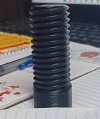
70mm length by 30mm diameter!

...
This bolt was overboard on sizing but for testing purposes is why I chose the sizing. I am still getting some, not much, seaming.
Seth
P.S. There was a "seam" option in the slicer that seems to be clicked every time I print, i.e. whether or not I click it or not. So, maybe it happened again. I will attempt a metric bolt again to test with testing all options in the slicer. Sorry for the poor photo quality. My phone is punk about photography. I will try a real camera next time.
silver2row
Senior Member
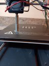
Not yet. No sir. I usually print them upright.
silver2row
Senior Member
Okay, you got it!
sacherjj
Member
Not going to work well as you want 45 degree from the bed draft. Threads are best on axis with the bed normal. It could work if you have a bit of a flat (think of a D shaped bolt when looking down at it). I have a design that prints half a thread flat on its side, which works fine. This can be used to join parts as Bambu did with their marble run. They use cap nuts to hold together and it works really well.
silver2row
Senior Member
Okay, I am not completely sure of what exactly bed draft is currently. I printed something I found recently from McMaster-Carr in .step format and imported it into Alibre and then exported it as a .stl formatted file.
Anyway, I need to figure out exactly how they are producing the final product so well. Years from this day, I may figure it out. Right now, I am on basics.
Seth
P.S. I printed the upright drilled head bolt like it showed. It worked out! Wait for photo...

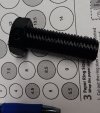
It is pretty neat. Real threading and a hex head at 3/4" * 2 1/4" but has a TPI of 2.5mm. I am not sure what happened... Oh! I know. When I exported the file to .stl format, I actually saved it as metric. Blah. Anyway, good-ole bolt for now.
Anyway, I need to figure out exactly how they are producing the final product so well. Years from this day, I may figure it out. Right now, I am on basics.
Seth
P.S. I printed the upright drilled head bolt like it showed. It worked out! Wait for photo...

It is pretty neat. Real threading and a hex head at 3/4" * 2 1/4" but has a TPI of 2.5mm. I am not sure what happened... Oh! I know. When I exported the file to .stl format, I actually saved it as metric. Blah. Anyway, good-ole bolt for now.
Hi,
I am new to Alibre CAD and have mostly found it intuitive to use, however, I am interested in how you managed to make it make threads. Is there a script that generates modeled threads like Fusion 360? Or did you manually model these threads? As I don't have access to a resource like the machinist handbook I have no clue how to manually model accurate threads.
I am new to Alibre CAD and have mostly found it intuitive to use, however, I am interested in how you managed to make it make threads. Is there a script that generates modeled threads like Fusion 360? Or did you manually model these threads? As I don't have access to a resource like the machinist handbook I have no clue how to manually model accurate threads.
Stu3d
Senior Member
Welcome to the forum.Hi,
I am new to Alibre CAD and have mostly found it intuitive to use, however, I am interested in how you managed to make it make threads. Is there a script that generates modeled threads like Fusion 360? Or did you manually model these threads? As I don't have access to a resource like the machinist handbook I have no clue how to manually model accurate threads.
Threads have to be modelled if you wish to 3d print them.
There are some recent links to videos and other thread related resources here https://www.alibre.com/forum/index.php?threads/watching-and-performing-actions-on-bolts.24791/
It is worth putting the version of Alibre you have in your signature, it will enable people to give you relevant help if you have questions.
silver2row
Senior Member
@Hilmi ,
Hello there, and yeppers. Working with threads is "easy" at times. It really depends on your requirements. Start with a circle in sketch mode, then extrude it to start in non-sketch mode.
Once it is extruded, pick your plane and return to sketch mode. If you chamfered the solid, round bar in the last extrusion, we can use The Crib Sheet to better explain:
ThreadProfileSketchCribSheet.pdf is what to search for under these headers.
So, chamfered round bar from extrusions in Alibre Atom3D or another version, whichever you are using from Alibre, needs to have the longest horizontal line on "top" of the non-chamfered section of the round bar extrusion.
Then, make a line diagonally downward to a shorter line. That shorter line is parallel to the longer line. Then, close your polygon with a diagonal line up and to the left. So, like a circle of motion with lines that are a polygon. Four sides and the upper and lower lines are both parallel to one another.
Make this form of lines, the polygon, close to the solid, extruded round bar tip with it being around the chamfer.
Please send in a photo of your build from this point forward and I try to explain better. Others here are way more experienced in this matter. So, it may help them to help you if you allow for their guidelines and answering their questions and/or concerns could not hurt.
Seth
silver2row
Senior Member
How do you place the type of Alibre one uses?Welcome to the forum.
Threads have to be modelled if you wish to 3d print them.
There are some recent links to videos and other thread related resources here https://www.alibre.com/forum/index.php?threads/watching-and-performing-actions-on-bolts.24791/
It is worth putting the version of Alibre you have in your signature, it will enable people to give you relevant help if you have questions.
Seth
Edit your signature and add it in there.How do you place the type of Alibre one uses?
Seth
There are several posts on best practice for for this.
Don't want to go on & on & on & on & on & on
But enough info to help the experienced users help you.
Jim
Hi,@Hilmi ,
Hello there, and yeppers. Working with threads is "easy" at times. It really depends on your requirements. Start with a circle in sketch mode, then extrude it to start in non-sketch mode.
Once it is extruded, pick your plane and return to sketch mode. If you chamfered the solid, round bar in the last extrusion, we can use The Crib Sheet to better explain:
ThreadProfileSketchCribSheet.pdf is what to search for under these headers.
So, chamfered round bar from extrusions in Alibre Atom3D or another version, whichever you are using from Alibre, needs to have the longest horizontal line on "top" of the non-chamfered section of the round bar extrusion.
Then, make a line diagonally downward to a shorter line. That shorter line is parallel to the longer line. Then, close your polygon with a diagonal line up and to the left. So, like a circle of motion with lines that are a polygon. Four sides and the upper and lower lines are both parallel to one another.
Make this form of lines, the polygon, close to the solid, extruded round bar tip with it being around the chamfer.
Please send in a photo of your build from this point forward and I try to explain better. Others here are way more experienced in this matter. So, it may help them to help you if you allow for their guidelines and answering their questions and/or concerns could not hurt.
Seth
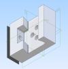
I really do appreciate your detailed response and it is obvious that you have gone to great lengths to explain it; however, I do find it hard to interpret the instructions purely from text. As a person who used to work on implementing Lean practices in companies, I used to preach that instructions with no explanatory drawings lead to errors in implementation, we used to describe to people how to draw an elephant from text only and the results were rather comical even when I used to give very precise instructions. As to what I am working on, it is a dovetail clamp for mounting accessories under a telescope. The clamp will have 3D printed threads (For example M6 size to move the movable jaw via a captive nut. While heated threaded inserts are the better engineering solution, they will drive the cost up significantly, makes more sense to 3D print the threads and then just clean them up with tap. I have attached a screenshot of how far I have reached with this design.
Attachments
Stu3d
Senior Member
Seth was describing what Harold shows in this video below. I think some of the other Ex Machina or Alibre Youtube videos show similar methods.Hi,
I really do appreciate your detailed response and it is obvious that you have gone to great lengths to explain it; however, I do find it hard to interpret the instructions purely from text. As a person who used to work on implementing Lean practices in companies, I used to preach that instructions with no explanatory drawings lead to errors in implementation, we used to describe to people how to draw an elephant from text only and the results were rather comical even when I used to give very precise instructions. As to what I am working on, it is a dovetail clamp for mounting accessories under a telescope. The clamp will have 3D printed threads (For example M6 size to move the movable jaw via a captive nut. While heated threaded inserts are the better engineering solution, they will drive the cost up significantly, makes more sense to 3D print the threads and then just clean them up with tap. I have attached a screenshot of how far I have reached with this design.

silver2row
Senior Member
@JimCad ...yes sir. I got it. Look at my signature and detailed exploratory ideas!Edit your signature and add it in there.
There are several posts on best practice for for this.
Don't want to go on & on & on & on & on & on
But enough info to help the experienced users help you.
Jim
Seth
P.S. The modern but irrefutable line reads, "Stay there and someone will find you." Classic!
silver2row
Senior Member
And yes sir to you there...I understand. Long scripts are a thing of the past. Internet.Hi,
I really do appreciate your detailed response and it is obvious that you have gone to great lengths to explain it; however, I do find it hard to interpret the instructions purely from text. As a person who used to work on implementing Lean practices in companies, I used to preach that instructions with no explanatory drawings lead to errors in implementation, we used to describe to people how to draw an elephant from text only and the results were rather comical even when I used to give very precise instructions. As to what I am working on, it is a dovetail clamp for mounting accessories under a telescope. The clamp will have 3D printed threads (For example M6 size to move the movable jaw via a captive nut. While heated threaded inserts are the better engineering solution, they will drive the cost up significantly, makes more sense to 3D print the threads and then just clean them up with tap. I have attached a screenshot of how far I have reached with this design.
Seth
P.S. If I was so eloquent in typing, I would have typed me up some books by now on some subject matter. Anyway, I hope you get what you are looking to find. And yes, @Stu3d was correct. I was using some ideas from @HaroldL and his video directed at me (I think). Anyway, good luck. There are more skilled Alibre users. I am a mouther from southern LA. Excuse the Elephant episode on my part...
I have a very old 3D printer (2016) but in my experience 3D printed threads would fail quite quickly in real life use. I would have thought the brass inserts would be far better. (just my view)Hi,
I really do appreciate your detailed response and it is obvious that you have gone to great lengths to explain it; however, I do find it hard to interpret the instructions purely from text. As a person who used to work on implementing Lean practices in companies, I used to preach that instructions with no explanatory drawings lead to errors in implementation, we used to describe to people how to draw an elephant from text only and the results were rather comical even when I used to give very precise instructions. As to what I am working on, it is a dovetail clamp for mounting accessories under a telescope. The clamp will have 3D printed threads (For example M6 size to move the movable jaw via a captive nut. While heated threaded inserts are the better engineering solution, they will drive the cost up significantly, makes more sense to 3D print the threads and then just clean them up with tap. I have attached a screenshot of how far I have reached with this design.
Jim


