What's new

Watching and Performing Actions on Bolts!

sacherjj

Member
One thing on 3d printed threads. While they are normally 60 degrees, there is advantages with 3d printing to limit deviation of a surface to 45 degrees from up. So a 60 degree thread is 15 degrees pas the sweet spot. It will usually work, but not as pretty. If you are printing both sides of the threads, going with 90 degree angle can make it print cleaner.
 

silver2row

Senior Member
Thank you for the advice. My inch bolt turned to metric in the .stl format save created some peculiar slicing objects.

I will try the 90 degree angle for 3D and keep the 60 or 55 degree base for some threading on the lathe, i.e. that is if I make it that far.

Seth

P.S. also, dually noted. The metric bolt saved as metric did not show any peculiarities in the CURA slicer program. I am thinking of purchasing the Simplify3D source if it can attempt imperial units for printing.
 

silver2row

Senior Member
I have been building a large standoff with metric type threads. Anyway, here it is...
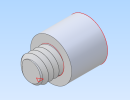
Stand_Off.png

Also...not just showing off ideas but indulging in other ideas where I cannot change things in my Alibre Atom3D source:

The shoulder bolt photo of a CAD drawing below has me thinking of "how!"
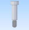
shoulder_bolt.png

What I was sold and what is listed are similar but not quite the same.

My main concern is the utilization of other technical skills relating to the shoulder bolt...

1. A line through the middle allows for extra advancement
2. It is almost like there are two lines on many planes.
a. One for intersection and another opposite for intersection of threads, the actual shoulder, and smaller-noticeable built parts like the interior hex in the head.
b. There are lines, with a perspective from photo viewing definitions, within the threads that run 60 to 55 degrees.
3. The lines in the threads are helix angles in between the crest(s) and root(s).

Anyway, here it is below. I am maybe wrong with respect to the lines of the helix angles that do or do not exist in the above diagram/CAD.
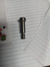
shoul.jpg

I am knowingly "gibberish'ing" here and I dislike as much as others do but...

1. I want to learn more about bolt building.
2. I first wanted to learn CAD with thinking it could turn me into an advantageous user and builder.
3. "Fitting in is half the battle!"

Seth

P.S. Does anyone know how to root and crest the planes on threads and if so, is anyone willing to help or create a group for others like me who want to learn? I am new and probably creating a too-much, too-soon scenario. Okay. Done for now.
 

HaroldL

Alibre Super User
The 60 degree form I gave you is a good starting point when learning how to create the helical sharp V thread. There is a crest and root form in the specs and this link may help with you to understand how they are created within the profile sketch.


There is also this crib sheet


that I placed in the resources section of the forum some time ago. Some users have found it helpful, Joseph has even mentioned it in one of his videos about creating threads.

 
Last edited:

silver2row

Senior Member
Thank you. I will check it out. I saw the short video and I will perform the actions on it soon (again and again) until fruition!

Seth
 

silver2row

Senior Member
Okay and So,

Outside of "Quick and Easy," which I am still trying to figure out here, I see in the Helical Cut Dialog Box there is an Advanced Section with Start and Stop Conditions.

Would the Start and Stop Conditions in the photo below have anything to do with the angle of the Helix Angle around Root and Crest?

Start_End_Conditions.png

Outside of that idea and going back to the video:


I am having a minor issue with the bottom line which is the Pitch divided by Four section in the video. I am using metric, also.

For the major and minor diameter, the minor diameter from the video seems to be an open set of two lines that will inevitably be closed in some form.

What is the form? Is it triangular or is it going to be some type of polygon like a trapezoid?

Also, I cannot create the major and minor diameters of the Triangle/Trapezoid yet because of the fact that I cannot highlight my Construction Lines on the Cylinder edging.

Seth

P.S. So, hopefully, I am making some sense here.
 

DavidJ

Administrator
Staff member
Would the Start and Stop Conditions in the photo below have anything to do with the angle of the Helix Angle around Root and Crest?
The start and end conditions are used for making springs or similar - not commonly used for screw threads.
 

silver2row

Senior Member
@DavidJ ...thank you. I was not familiar with the start and end conditions yet. I tested them, hilarity ensued. Now, I know they are mostly for springs or similar items.

Seth

P.S. In any case here, thank you everyone for tolerating me so far.
 

HaroldL

Alibre Super User
I am having a minor issue with the bottom line which is the Pitch divided by Four section in the video. I am using metric, also.

For the major and minor diameter, the minor diameter from the video seems to be an open set of two lines that will inevitably be closed in some form.

What is the form? Is it triangular or is it going to be some type of polygon like a trapezoid?

HI Seth, the two reference lines shown in the video are actually the major radius and minor radius and are sketched on the sketch plane as a guide to place the thread profile sketch on. The two side lines are dimensioned at 60 degrees and the final form is a trapezoid. The bottom line of the trapezoid is dimensioned at Pitch/4 and is sketched on top of the minor radius line.

If you click on the link I provided above you can download the crib sheet and data sheet that I placed in the Resources a while ago. The crib sheet has images that illustrate how to create the thread profile and position it to create the thread.
I actually updated the link to get you to the latest version of the zip file.

Also, I cannot create the major and minor diameters of the Triangle/Trapezoid yet because of the fact that I cannot highlight my Construction Lines on the Cylinder edging.
The major and minor radius lines are just sketched on the plane and dimensioned from the axis or origin depending on how the part is oriented in the workspace. IF you need to project the edges of the fastener into the sketch then select the Project to Sketch tool, set it to create reference geometry and to maintain association with source entity, then select the edges OR click on the end face of the part or if chamfered click on the face of the chamfer and project to sketch. That will give you more reference lines to work with.

Let me know if any of this made any sense to you.
 

silver2row

Senior Member
HI Seth, the two reference lines shown in the video are actually the major radius and minor radius and are sketched on the sketch plane as a guide to place the thread profile sketch on. The two side lines are dimensioned at 60 degrees and the final form is a trapezoid. The bottom line of the trapezoid is dimensioned at Pitch/4 and is sketched on top of the minor radius line.

If you click on the link I provided above you can download the crib sheet and data sheet that I placed in the Resources a while ago. The crib sheet has images that illustrate how to create the thread profile and position it to create the thread.
I actually updated the link to get you to the latest version of the zip file.


The major and minor radius lines are just sketched on the plane and dimensioned from the axis or origin depending on how the part is oriented in the workspace. IF you need to project the edges of the fastener into the sketch then select the Project to Sketch tool, set it to create reference geometry and to maintain association with source entity, then select the edges OR click on the end face of the part or if chamfered click on the face of the chamfer and project to sketch. That will give you more reference lines to work with.

Let me know if any of this made any sense to you.

Hello @HaroldL ,

Seth here. Thank you first off. I will test out the reference geometry some more to fine tune it and see if I can get it to work. I will look at the crib sheet again also.

I quickly brazed through the crib sheet(s) that had the .pdf files and other files (I think). I will research via our chats back and forth for the correct docs. on the crib sheet status.

Right and I did watch the video plenty of times...

Pitch/4 or (1/12)/4 like in the video... I am not keen on metric pitch all that much. I will need to relearn it soon. So, instead of TPI/4 like I stated earlier, (1/12)/4, it would be the actual Pitch/4. Okay.

In any light here,

1. I make my horizontal line (left to right)
2. Then, I make a diagonal line from the horizontal line
3. I then try to get the same equal constraint for the diagonal line on a new line
4. Number 3. from above is when I run into issues
5. The lines never have the same angle or equality

I have attempted your video and all works well. This is not the issue.

Seth

P.S. I will look more into making trapezoids on Atom3D!
 

silver2row

Senior Member
I just figured it out from the crib sheet. It is a closed trapezoid! Dir!

I was trying to make the open trapezoid so I could alter the lines horizontally which makes no sense.

Seth

P.S. Here is the difference...

trapezoidal_pitch_count.png
 
Last edited:

Hilmi

Member
Many thanks for this wonderful video :) May I request that you use your ninja skills to create a file pack of standard dies for inner and outer threads as files we can download and directly use in our drawings as cutting tools?
 

Stu3d

Senior Member
Many thanks for this wonderful video :) May I request that you use your ninja skills to create a file pack of standard dies for inner and outer threads as files we can download and directly use in our drawings as cutting tools?
@Ex Machina produced that great video amongst many others, I'm afraid my ninja skills pretty much extend to fries in an air fryer!
 
Top