What's new

Shell Tool Behavior

JEdgarEE

Member
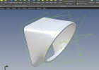
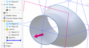
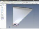
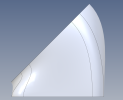
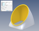
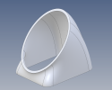
Attached is a file that has an error in the shell operation. I am trying to shell out both flat surfaces to make an odd tube-like object with a wall thickness of 0.5". Can someone explain why it results in an error? I believe it has something to do with the sketch that's on the offset ZX plane. Also, some wall thicknesses have better results than others.

Latest V27 Expert fully Maintenanced running on a Windows 11 machine. AMD Ryzen 9 7950X, AMD RX6950, 64GB DDR5

Kind regards,
Joey
 

Attachments

  • BASE_V3.AD_PRT
    422.5 KB · Views: 12

Ken226

Alibre Super User
For what you want to accomplish, Shell isn't the appropriate tool. Shell will hollow out the object, which leaves one end closed. Attempting to shell the opposite end results in the shell tool trying to create a shell on the wall that has a thickness equal to your desired shell thickness. The shell tool appears to not like leaving a wall thickness equal to or less than zero.

To make it a tube, create sketches at each end then use a loft remove operation. That should get you what you want.

Like this:

1694626632240.png
 

Attachments

  • BASE_V3.AD_PRT
    701 KB · Views: 2

HaroldL

Alibre Super User
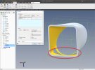
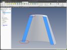
The original part did have the front and end faces selected.

Original Shell.jpg

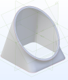
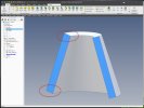
I used a Delete Face and Thicken to get this result.

Thicken vs Shell.jpg

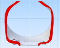
I suspect that Shell had an issue with the bottom curvature.
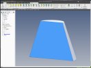
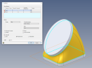
When I used Loft Cut and used sketches that were offset .500 I got these odd results.

Odd Loft Cut Results.jpg

I'd submit this model to Support and Development for eval.
 

JEdgarEE

Member
The original part did have the front and end faces selected.

View attachment 39650

I used a Delete Face and Thicken to get this result.

View attachment 39651

I suspect that Shell had an issue with the bottom curvature.
When I used Loft Cut and used sketches that were offset .500 I got these odd results.

View attachment 39654

I'd submit this model to Support and Development for eval.
Yea, I created a surface and thickened it to get the part I somewhat wanted... How do I submit an S&D ticket? Thanks for the responses, folks.
 

Attachments

  • BASE_V2.AD_PRT
    2.8 MB · Views: 2

Joseph_L

Administrator
Staff member
Well I deleted face and then thickened it into a solid, and then re-read the thread and it turns out Harold beat me to it! Great minds think alike Harold! Here is the part if it helps any.1694639449192.png
 

Attachments

  • BASE_V3.AD_PRT
    639 KB · Views: 3

JEdgarEE

Member
Well I deleted face and then thickened it into a solid, and then re-read the thread and it turns out Harold beat me to it! Great minds think alike Harold! Here is the part if it helps any.View attachment 39659
This seems to work but creates another problem. Load this file into an assembly and you can't reference the 45-degree flat surface to anything....
 

Attachments

  • DESKTOP_TEST_FIXTURE.AD_ASM
    352.5 KB · Views: 5

Joseph_L

Administrator
Staff member
This seems to work but creates another problem. Load this file into an assembly and you can't reference the 45-degree flat surface to anything....
Cool use of images! Unfortunately though I'm not getting the assembly since I don't have the parts that go in it. Would you be able to package the assembly and upload the package?
 

Joseph_L

Administrator
Staff member
I think I see what you mean based on what you said. The face from the surface thicken isn't being recognized as planar. Try this.
 

Attachments

  • BASE_V3.AD_PRT
    672 KB · Views: 3

JEdgarEE

Member
You appear to be running V28 when you created that file. I can't open it. V28 isn't out yet, correct? It's an Acoustic test setup for NASA's next space suit. I'm actually the EE on the task designing the comms unit. It is fun stuff!

1694707185905.png
 

JEdgarEE

Member
My mistake! See this one
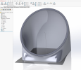
I agree this kind of works. You fixed(adjusted, lose 0.001") the 45-degree surface but the bottom surface doesn't play nicely. The only reason this works on the 45-degree surface is because the loft feature is tangent there. The bottom surface is completely non-flat, and I lose almost 0.4" of material to flatten it out using the method provided. My attached base_v2 part early on in this forum discussion uses this method. Ideally the loft and shell operations should work. I need them to work as if I'm running a business which are my intentions. I got tired of these hacks back using Freecad. I fluidly use SW, Pro E, and other industry parametric modeling applications at my current employer. FYI, the dome in the packaged assembly is impossible to create in Alibre :) I made it in SW and imported as a step.

I thought Alibre could handle all the basic parametric modeling operations (shell/loft included) without the simulation and fancy features of the industry giants. I thought that's why it was cost effective. I also wanted to help the underdog and get myself started on a personal endeavor. However, I feel like I'm wasting time/money on a product that kind of works. Just last week I quoted and geared up to purchase the FEA addon. But, very hesitant now. In the packaged assembly I provided there is an air duck part. The shell feature worked to create it but now if you just open the edit window on the shell operation it errors out. It's getting frustrating. It doesn't seem like this application is ready for release. I submitted a formal support request. Joseph your title in the forums says you're a staff member, is that correct? Do you work for Alibre? My apologies if I'm coming off harshly, I just wanted this to work.
 

HaroldL

Alibre Super User
The bottom surface is completely non-flat
To explain why the bottom is not flat I created a sample part and, using configurations, applied a shell and a thickened surface to compare their results.

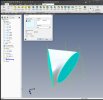
Starting with a conical feature" shown with a Precise Section View...
Conical Feature.jpg

I first applied a .200" shell.
Take note of the end surfaces...
Shelled Conical Feature.jpg

I then applied a delete face to remove the two end faces and thicken surface of .200".
Again, note the end surfaces...
Thicken Conical Feature.jpg

It appears to me that Shell will thicken the part along the X,Y, or Z axes while Thicken is normal to the originating surface. I think that explains why the end face of your part is not flat, the thickness face (?) of the part is normal to the surface and follows all its curvature. Thus requiring a secondary operation to "flatten" the end with an extrude cut.

Knowing this, it may be advantageous to modify your original loft by adding an extra sketch to extend the part to allow for trimming to the size your design requires.
IF shell would not fail then the end face would be flat.

As a side note, it would be interesting to see how the other CAD programs perform these same operations.
 

JEdgarEE

Member
To explain why the bottom is not flat I created a sample part and, using configurations, applied a shell and a thickened surface to compare their results.

Starting with a conical feature" shown with a Precise Section View...
View attachment 39675

I first applied a .200" shell.
Take note of the end surfaces...
View attachment 39674

I then applied a delete face to remove the two end faces and thicken surface of .200".
Again, note the end surfaces...
View attachment 39673

It appears to me that Shell will thicken the part along the X,Y, or Z axes while Thicken is normal to the originating surface. I think that explains why the end face of your part is not flat, the thickness face (?) of the part is normal to the surface and follows all its curvature. Thus requiring a secondary operation to "flatten" the end with an extrude cut.

Knowing this, it may be advantageous to modify your original loft by adding an extra sketch to extend the part to allow for trimming to the size your design requires.
IF shell would not fail then the end face would be flat.

As a side note, it would be interesting to see how the other CAD programs perform these same operations.
I understand the thicken tool works with normal vectors. The thickening tool seems to be working as intended. However, for the part I need the normal goes acute and obtuse to 90 degrees from the sketch plane. Thus, a simple extrude cut for normal vectors larger then 90 isn't enough. I would also need to extrude out areas with normal's less then 90 degrees. Extruding out would then insert straight wall features and not curve like the intended design. Your conical example is simplified. SolidWorks and Pro E handle this with no problem. I've even been able to produce what I needed with FreeCAD... 1694720600142.png
 

HaroldL

Alibre Super User
Your conical example is simplified.
My example was simple only to illustrate the difference between shell and thicken. The fact that the thicken normals go acute and obtuse to 90 degrees tells me that the surface is not normal the the sketch plane. That's why I suggested added an extra sketch and extension to the loft to give you an area where you could extrude cut to the design size.

Extruding out would then insert straight wall features and not curve like the intended design.
Do you mean the thickness surface needs to be curved or just the side surfaces?

Another method that may help is to create two extrusions from the current sketches. Then Loft from face to face. Note that I set the Face Take Off to Perpendicular.
1694741215987.png

The resulting shell looks promising as long as it fits your design requirements. I selected all the faces of the extrusions for removal in the shell
1694741184495.png

1694741540872.png

1694741286128.png
 

Attachments

  • BASE_V3-3 FACE-TO-FACE LOFT.AD_PRT
    1.2 MB · Views: 2
Top