2D drawings communicate manufacturing requirements, data for patent protection, assembly instructions, and much more. Capture geometry for milling 2.5 axis parts or lasercutting / waterjet manufacturing.
For CNC / Laser / WaterJet
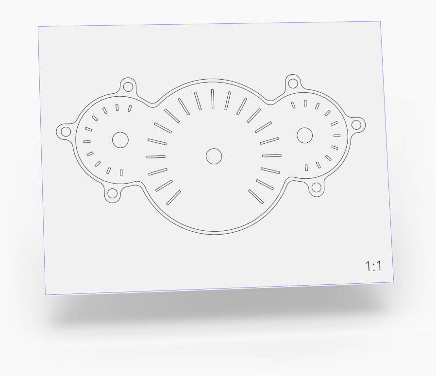
Create 1:1 views or scaled views from any angle and export for use in downstream applications like 2.5 axis milling, laser cutting, or waterjet cutting.
Templating System
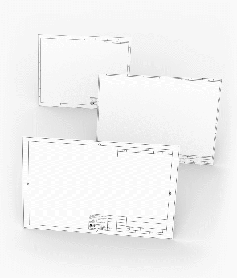
Choose from built-in ANSI, ISO, and JIS templates or create your own. Or, if you're using the drawing to prepare 2D geometry for milling or laser cutting, just use a blank template.
Exploded Views
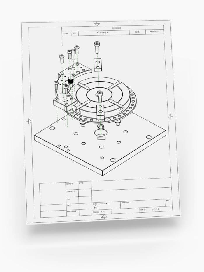
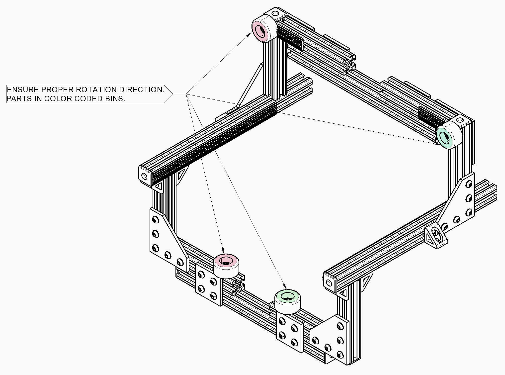
Create exploded views in an assembly workspace and transfer them into 2D drawings to make quick assembly instructions and visualize how the model comes together.
Hidden Lines
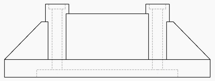
Reveal hidden lines to document internal structures or otherwise obscured details. Toggle hidden line visibility for each view with a click.
Layers
A customizable layer system allows you to define the color, stroke pattern, and weight of figures and annotations. Change the appearance of standard figure types such as Hidden Line, Center Line, or Visible drawing wide, or create new layer styles and apply them to anything.
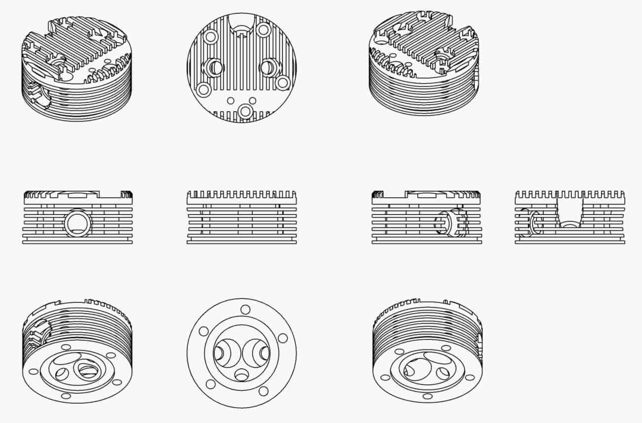
Standard Views
The start of any drawing is the creation of a standard view. Typically a standard view uses principal projection planes to represents something like Front, Top, or Right, but can include isometric views or any custom angle.
A drawing showing the 10 standard views
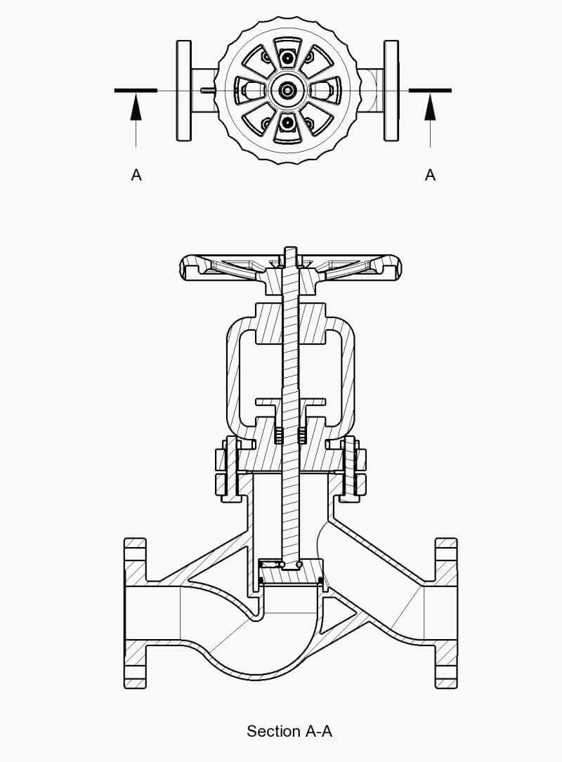
Section Views
Section views cut a part or multiple parts along the defined cutting plane to give visibility to hidden features and to display how multiple parts fit together. They are used when hidden lines or other methods are not suitable.
Detailing one or more cross sections is often the best way to fully describe the geometry of a model.
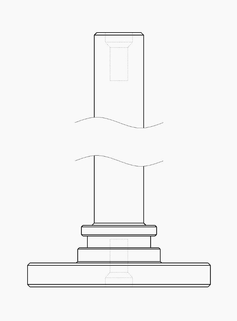
Broken Views
Broken views make it possible to display long or large components at a larger scale in a drawing by removing portions of the view that add no value to detailing. Very long parts might otherwise be tedious or impossible to detail on a single sheet.
Multiple extension line styles are available and the gap width is easily customized.
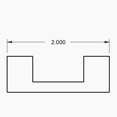
Dimensions
Many types and styles of dimensions are available to ensure succinct and compliant communication of design intent.
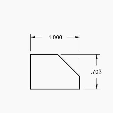
Regular Dimension
The most common dimension type shows the distance or angle between two figures.
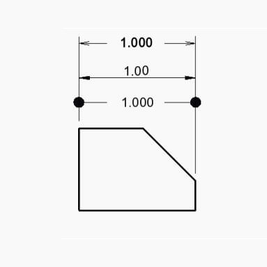
Gapped Dimension
Any dimension can have gapped dimension lines and extension lines.
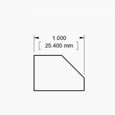
Dual Dimension
Show any or all dimensions in multiple units as needed.
Styles
Create custom styles for dimensions and apply them consistently.
User Input Fields
Easily populate common fields in a title block like Drawn Date, DWG Number, Drawn By, Sheet Number, and Sheet Scale.
Images
Import 2D image files into a drawing for reference, logos, or other applications.
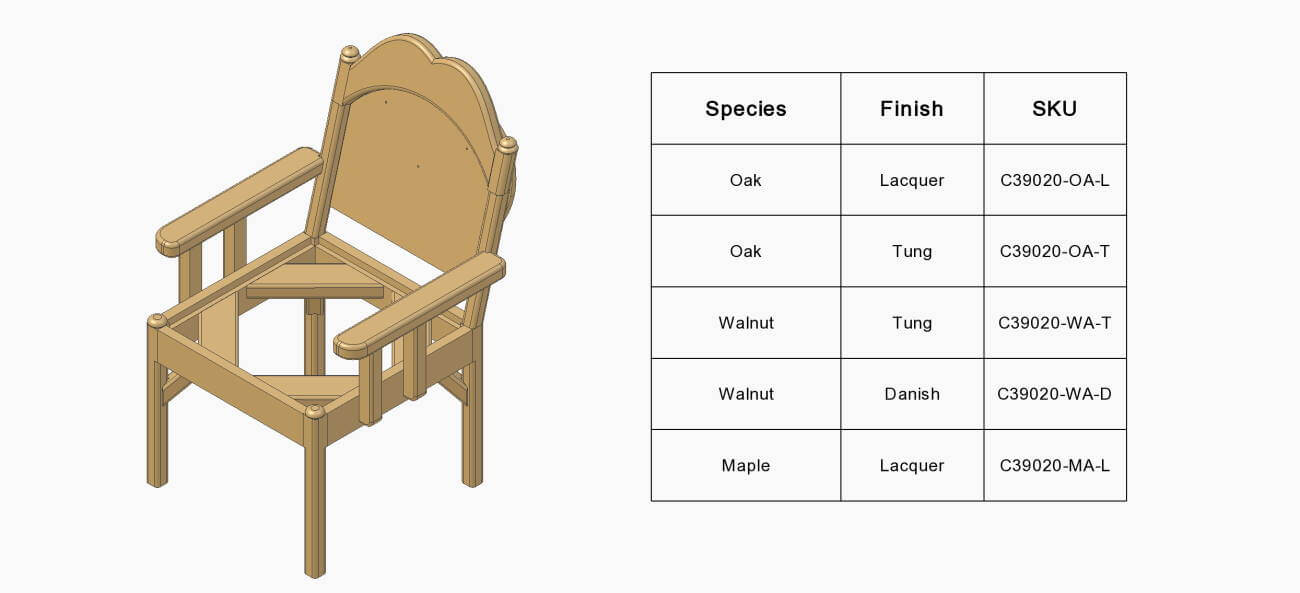
Tables
Create arbitrary 2D drawing tables of any size that you can manually populate with data. Tables can maximize clarity when many data points or combinations are needed.
Set the table to any layer to achieve the desired visual style and optionally export the table as a CSV file to open in other spreadsheet applications.
A table example showing various SKUs of the chair model based on a wood and finish combination.
Color Fill
Define areas of a drawing to manually fill with a color or hatch pattern. Adding color coding or pattern details to drawings can make a large difference in efficiency downstream when important manufacturing or assembly instructions need to be clearly communicated.
Manual Centerlines
Create centerlines between two edges when automatic centerline creation is not sufficient. Centerline chains can display centerlines through various model features.