Table of Contents
TopicsUnlocking the Potential of Plastics Through Design Integrity
In the universe of manufacturing, part design is the celestial body around which the orbits of product functionality, manufacturability, and market success revolve. Particularly in injection molding, part design isn't just about aesthetics or dimensions; it's about envisioning a component's journey from granular plastic pellets to a durable, functional part integral to a complex assembly.
Decoding Part Design in Injection Molding
Designing parts for injection molding, like other manufacturing processes, is a delicate balance of mechanical properties, product design, cost efficiency, and performance. Unlike other manufacturing processes, however, injection molding necessitates a design approach that considers the behavior of plastic as it transforms from a molten state to a solid state within the confines of a precisely engineered mold. The designer must anticipate the flow of plastic, the impact of cooling rates, and the interplay between the part structure and the physical forces exerted by the molding machine.
The Pillar of Product Development
The significance of part design in product development is paramount. It is the blueprint that dictates the feasibility of manufacturing and sets the stage for the product's ultimate performance. In injection molding, the part design dictates the mold design, which in turn, influences cycle times, production costs, and the longevity of the mold itself.
A well-conceived part design can lead to a robust product with optimal functionality, longevity, and aesthetic appeal. Conversely, poor part design can result in manufacturing challenges, increased costs, and potential product failures. It's this high-stakes environment that elevates the role of the part designer from a mere contributor to a principal architect of a product's success.
A well-conceived part design can lead to a robust product with optimal functionality, longevity, and aesthetic appeal. Conversely, poor part design can result in manufacturing challenges, increased costs, and potential product failures. It's this high-stakes environment that elevates the role of the part designer from a mere contributor to a principal architect of a product's success.
Molding the Future: The Science of Plastics in Design
This guide is aimed at helping to speak the language of plastics more fluently. At the core of injection molding part design is a profound understanding of how plastics behave. This knowledge serves as the foundation upon which all design elements are constructed. But why is material behavior so critical in part design? The answer lies in the unique properties of plastics that can be both advantageous and challenging for designers.
The Nature of Plastic
Plastics are not a monolith; their properties vary immensely. From the tensile strength of nylon to the impact resistance of polycarbonates, the choice of material influences aspects of part design, and more significantly, the performance of the finished part. As compared to metal, wood and other materials, plastics have a low modulus and tend to creep. They have a viscoelastic nature, meaning they respond differently to a force applied at a high rate rather than a low. When looking at the stress-strain performance of plastic, an often omitted part of the conversation is to ask, “But at what strain rate does this apply to?”
Fun fact: Did you know mechanical thermostats in cars use a substance that is basically candlewax to detect the cars temperature and open and close valves to regulate coolant flow? Like candlewax, plastics expand and contract greatly upon melting and solidifying respectively. These expansions and contractions are the chief driving elements of good part design.
Fun fact: Did you know mechanical thermostats in cars use a substance that is basically candlewax to detect the cars temperature and open and close valves to regulate coolant flow? Like candlewax, plastics expand and contract greatly upon melting and solidifying respectively. These expansions and contractions are the chief driving elements of good part design.
Selecting the Right Material
The material selection process involves considering the intended use of the product, the environment it will be exposed to, and the stresses it will endure. Will the part be exposed to high temperatures, chemicals, or physical impact? Does it need to be flexible or rigid, transparent, or opaque? Each of these questions guides the material selection and, consequently, the design nuances of the part.
Another important distinction is that some polymers are semi-crystalline while others are amorphous. Imagine your injection molding material is a plate of spaghetti. Now imagine every spaghetti noodle has a knot tied in it. When all the noodles are put together, it is easy to imagine all of the knots in the spaghetti cause the noodles to stick together more. Amorphous is like having spaghetti noodles without knots, and semi-crystalline materials are like having noodles with knots. Amorphous and Semi-Crystalline have different material properties as noted below:
Another important distinction is that some polymers are semi-crystalline while others are amorphous. Imagine your injection molding material is a plate of spaghetti. Now imagine every spaghetti noodle has a knot tied in it. When all the noodles are put together, it is easy to imagine all of the knots in the spaghetti cause the noodles to stick together more. Amorphous is like having spaghetti noodles without knots, and semi-crystalline materials are like having noodles with knots. Amorphous and Semi-Crystalline have different material properties as noted below:
| Property | Semi-Crystalline | Amorphous |
|---|---|---|
| Structure | Ordered crystalline regions interspersed with amorphous areas. | Random, less ordered arrangement without distinct crystalline regions. |
| Optical Properties | Often opaque or translucent due to light scattering. | Usually transparent as there is no light scattering from crystalline boundaries. |
| Thermal Properties | Distinct melting point; crystalline regions melt at a specific temperature. | Gradual softening as temperature increases, without a sharp melting point. |
| Mechanical Properties | Generally higher tensile strength and better wear resistance. | Less rigid, may have better impact resistance due to the flexibility of the amorphous structure. |
| Density | Tend to be denser due to closely packed chains in crystalline areas. | Less dense because of the less ordered molecular structure. |
| Chemical Resistance | Often more chemically resistant due to tight molecular packing. | May be more prone to chemical attack due to the more open structure. |
| Permeability | Lower permeability for gases and liquids because of the crystalline structure. | Higher permeability due to the free volume in the amorphous regions. |
| Shrink | Tends to be higher shrink than Amorphous | Tends to be lower shrink than Semi-Crystalline |
This table presents a simplified overview, and the properties can vary widely within each class of materials depending on their specific chemical structure and processing.
So what materials are Semi-Crystalline and Amorphous?
So what materials are Semi-Crystalline and Amorphous?
| Material Type |
Semi-Crystalline Polymers |
Amorphous Polymers |
|---|---|---|
| Common Polymers |
Polyethylene (PE) Polypropylene (PP) Polyethylene Terephthalate (PET) Polybutylene Terephthalate (PBT) Polyoxymethylene (POM or Acetal) |
Polystyrene (PS) Polymethyl methacrylate (PMMA) Polycarbonate (PC) Acrylonitrile butadiene styrene (ABS) Polyvinyl chloride (PVC) - un-plasticized Polyvinyl alcohol (PVOH) |
| Engineering Polymers |
High-performance polyethylene (HPPE) Polyphenylene sulfide (PPS) Partially crystalline PEEK |
Polyetherimide (PEI) Polyetheretherketone (PEEK) - amorphous grades Polysulfone (PSU) |
| Biopolymers |
Polylactic acid (PLA) Polyhydroxyalkanoates (PHAs) |
Atactic polystyrene Certain Biodegradable Polymers e.g. PBS, PCL in amorphous forms |
Design for Manufacture (DFM): The Heart of Smart Design
At its heart, DFM involves designing parts with the manufacturing process in mind. It is about understanding the capabilities and limits of the injection molding process and leveraging this knowledge from the earliest stages of part conception. DFM aims to minimize the complexities in manufacturing, reduce material waste, and avoid costly design modifications down the line.
The integration of DFM principles into part design begins with simplification. By simplifying geometries, reducing part counts, and optimizing the part for the molding process, designers can significantly reduce the risks of defects and streamline the production process.
The integration of DFM principles into part design begins with simplification. By simplifying geometries, reducing part counts, and optimizing the part for the molding process, designers can significantly reduce the risks of defects and streamline the production process.
Uniform Wall Thickness
Design parts with consistent wall thickness to prevent issues like sink marks, warping, and uneven cooling, which can lead to part stress and distortion. The image below shows regional thickness in the center of the part, that can and should be eliminated, which is done in the second image.
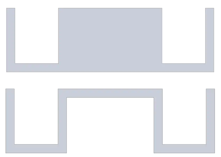
Varying wall thickness can also prevent the mold from being filled adequately. If thinner and thicker regions are an absolute necessity, make sure that the flow starts in the thick region and fills the thin regions last. Make sure that flow does not go from thick regions to thin regions and then through to thick regions again, as this will cause significant pressure drops that effect the integrity of the mold capabilities. Sometimes this needs to happen, like in the case of molding living hinges, but should be avoided. The transition from a thick to a thin region should be as gradual and smooth as possible.
Rationalizing Undercuts
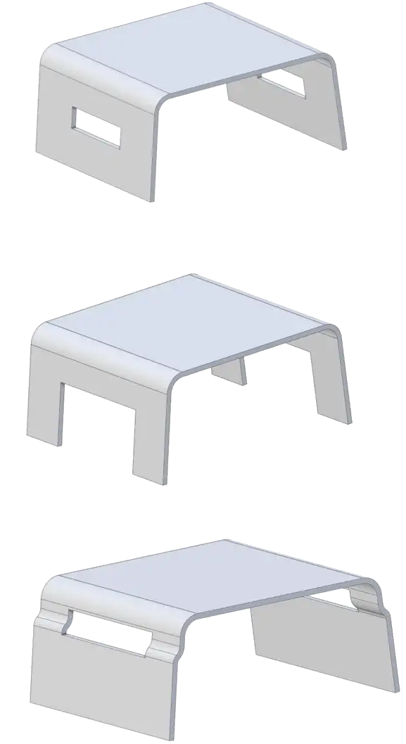
While undercuts are sometimes necessary for part function, they complicate the mold design and the molding process. Rationalizing these features or designing alternatives can reduce costs and complexity. Take a look at the images below. The first image would require expensive and complex tooling to be able to create the holes in the side of the part. This can be avoided simply by removing material below the cutouts as shown in the second image. If it is absolutely necessary to have a “hole” rather than simply removing material from the bottom, a vertical cut through a section with extra draft can be an excellent solution that simplifies the tooling a great deal.
Adequate Draft
Including sufficient draft angles on walls perpendicular to the mold opening direction is crucial for easy part ejection and to prevent damage to the part or the mold. Take a look at the image below- You’ll find the yellow part can easily pull away from both the red core and green cavity due to the angles built in to the wall. If the walls were all straight up and down, this would be much more difficult to eject the part from the core and cavities without damage to the part or tools. All features should be drafted for effective injection molding.

Correct Use of Ribs and Support Material
Strength in injection molded parts does not necessarily come from bulk. The strategic use of ribs and gussets can significantly increase part stiffness without compromising the uniformity of wall thickness. However, like any feature, they must be designed with care to prevent sink marks and ensure they do not overshadow the core geometric design principles.
Rib Thickness
Typically, ribs should be about 60% of the adjoining wall to avoid shrinkage issues. To be more precise, however, it is recommended to use .5 wall thickness for high amorphous and 0.75 wall thickness for semi-crystalline.
Rib Height
While the height of a rib can vary, it should be designed to provide the necessary support without becoming a hindrance during the molding process. Usually, a rib height of no more than 3 times the wall thickness should be used for most reliable results. Fillets at the base of the ribs should be about .25x the wall thickness for best results.
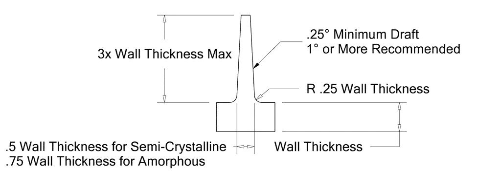
When there is too much material in a rib’s cross section, the material will shrink on cooling causing a phenomenon known as sink on the side of the wall opposite of the rib. This is undesirable for many reasons, including poor cosmetics and potential thermal and stress concentrations that can be avoided.
Gusset Placement
Place gussets at strategic locations to support load-bearing areas and to enhance the overall rigidity of the part without affecting the material flow.
Gradual Transitions
Where design constraints require thickness changes, ensure that the transitions are as gradual as possible to minimize stress concentrations and integrity of flow.
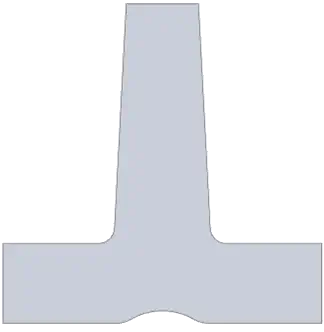
Take a look at the top image below. Imagine you were looking at the consistent thickness image and it was actually a cross section from the exhaust pipe of your car. How would the exhaust flow through it? Probably not well, as all those sharp angles and transitions would create a lot of turbulence and backpressure. Can you see the improvements in the bottom image? Make sure there are no sharp edges in the cross section of the part that a flow front will move over.
Take a look at the top image below. Imagine you were looking at the consistent thickness image and it was actually a cross section from the exhaust pipe of your car. How would the exhaust flow through it? Probably not well, as all those sharp angles and transitions would create a lot of turbulence and backpressure. Can you see the improvements in the bottom image? Make sure there are no sharp edges in the cross section of the part that a flow front will move over.
Hole Features
When designing for holes, through holes are preferred over bottoming holes, but with some setbacks as well.
Through holes have more options to be able to make in the tooling and feature more dimensional stability, as tooling can meet from both sides of the hole. However, when the flow front of the molding moves around a bottoming hole, it must split into two fronts as it moves around the hole. The two fronts then meet again on the other side of the hole. The place where the fronts meet is known as a weld line and creates a local area of weakness. Keep this in mind any time a feature splits a flow front into two parts. A bottoming hole will not do this.
Through holes have more options to be able to make in the tooling and feature more dimensional stability, as tooling can meet from both sides of the hole. However, when the flow front of the molding moves around a bottoming hole, it must split into two fronts as it moves around the hole. The two fronts then meet again on the other side of the hole. The place where the fronts meet is known as a weld line and creates a local area of weakness. Keep this in mind any time a feature splits a flow front into two parts. A bottoming hole will not do this.
Design for Manufacturing: Snap Fits
A common feature in molding is known as the snap fit. These allow for small ‘arms’ of plastic to snap over other pieces to hold parts together. How do we design these? A few important points:
• The snap fit should be sized so that the snap fit does not exceed 70% of the yield strain of the material at any point
• The snap fit arm should not be in a stressed state after it has been snapped
• It is common for the cross sectional dimensions of snap fit arms to diminish down their length- this saves material and makes for a more ideal stress profile for the arm.
But how do I calculate strain?
When you're calculating the strain due to bending in a beam with a rectangular cross section, the strain equation is typically derived from the basic principles of beam bending and material mechanics. The strain (ε) at a distance y from the neutral axis (which is the axis about which the beam bends and experiences zero strain) can be expressed as:

Where:
• ε is the strain at the distance y.
• y is the distance from the neutral axis to the point where the strain is being calculated. For a rectangular cross section, this value ranges from -h/2 to +h/2, where h is the height of the rectangular cross-section.
• ρ is the radius of curvature of the beam's bent axis. It's important to note that this radius of curvature changes along the length of the beam.
This equation is based on the assumption that the material of the beam is linearly elastic (i.e., it follows Hooke's Law) and that the deformations are small. The negative sign indicates that the strain is compressive above the neutral axis and tensile below it.
To relate this strain to bending, you often use the flexural formula:

Where:
• σ is the stress.
• M is the bending moment. (e.g. if you had a two meter long beam and you applied a force of 10 Newtons to it, M would be 20 Nm.)
• I is the moment of inertia of the beam's cross-sectional area. Often, for a rectangular cross section, the equation for I is given as:
• σ is the stress.
• M is the bending moment. (e.g. if you had a two meter long beam and you applied a force of 10 Newtons to it, M would be 20 Nm.)
• I is the moment of inertia of the beam's cross-sectional area. Often, for a rectangular cross section, the equation for I is given as:

Where:
• b is the width of the beam’s cross section.
• H is the height (or depth) of the beams cross section. H is the dimension perpendicular to the neutral axis and in the direction of the height of the bending moment is taken as h. In other words, it is the dimension across wich there is the largest variation in strain and stress due to bending.
• The factor 1/12 is a constant that arises from the integral calculation of the moment of inertia for a rectangular area
• The snap fit beam should be .5-.75x the main wall thickness in the direction of bending. Too thin and it won’t fill properly, too thick and it will have too much stress at the base.
• Draft is not normally dramatic enough to be added to calculations
Since strain is stress divided by the material's Young's modulus (E), the strain can also be expressed in terms of bending moment and geometric properties:

Where:
• E, again, is young’s modulus for the material you have chosen.
This equation gives you the strain at any point in a beam under bending, considering its material properties (through E) and geometric characteristics (I and y).
Thus substituting the equation for I into the equation, we have:
• E, again, is young’s modulus for the material you have chosen.
This equation gives you the strain at any point in a beam under bending, considering its material properties (through E) and geometric characteristics (I and y).
Thus substituting the equation for I into the equation, we have:
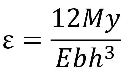
If your stress value is 70% or less of yield strain, you should be good to go.
What about overhangs and molding compatibility?
The image below shows a snap fit.

But there is a problem- how would a part like this be able to be ejected from the mold? Perhaps you recall the image from earlier- how would an overhang like a snap fit be able to be ejected from this?
It is possible to get tooling to work for overhangs, but should be avoided as it is expensive to do and may cause added wear to the tools. The simple solution- a pass-through shutoff!
Lets start by eliminating material directly under the snap fit overhang:
Lets start by eliminating material directly under the snap fit overhang:
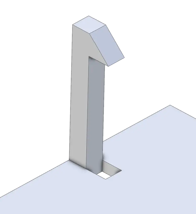
This eliminated material allows for the orange mold tooling to ‘pass through’ the main wall and allow for the overhang to be molded.
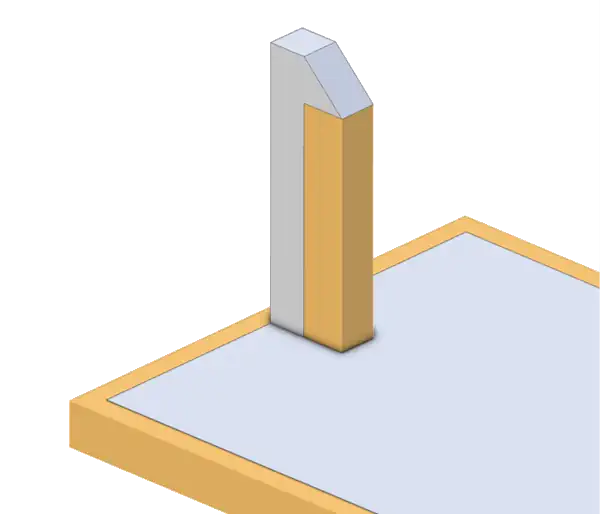
For simplicity, this was not shown with draft. You will notice the other part of the tooling will have to mold the top and sides of the snap fit feature, and come into contact with the pass through shutoff that creates the overhang on the snap fit. In areas where the two tools make contact, higher draft values will preserve the tooling life. Aim for 5° or more draft where tooling contacts other tooling.
Using Technology
Technological advancements in simulation software have empowered designers to predict outcomes more accurately than before. However, mold simulation technology has its limitations. As a rule of thumb, simulation is accurate in showing where distortions such as warp, sink, or shrink will occur, but the magnitude of such distortions can vary widely from the predictions of the simulation. To date, there is no replacement for understanding and following good injection mold design principles.
The Pros and Cons of Injection Molding
Advantages of Injection Molding
Injection molding is a highly efficient process for mass-producing plastic parts and components. One of its primary advantages is the ability to produce large volumes of parts with a high degree of consistency and repeatability. This uniformity is crucial for industries where precision is paramount, such as automotive and medical device manufacturing.
Another significant benefit is the ability to design and produce complex geometries that would be difficult or impossible to achieve with other manufacturing methods. Injection molding allows for intricate designs with precise detail, undercuts, and tight tolerances, opening a vast array of design possibilities.
Additionally, injection molding is cost-effective at scale. Although the initial cost of mold design and creation can be high, the per-part production cost is significantly reduced for large runs due to the speed of the manufacturing process. This makes injection molding an excellent choice for long-term production where the initial investment can be amortized over a high volume of parts.
Material selection is another advantage. A wide variety of plastics and polymers can be used in injection molding, allowing for material properties to be tailored to specific application needs such as flexibility, strength, or resistance to heat or chemicals.
Disadvantages of Injection Molding
Despite its many benefits, injection molding also has drawbacks. The upfront investment for tooling is substantial and can be prohibitive for small businesses or for products with a low production volume. This initial cost also makes it less ideal for prototyping compared to additive manufacturing processes like 3D printing.
The need for high-volume production to justify the initial costs means that injection molding is less flexible when it comes to scaling production up or down quickly. Design changes can be costly and time-consuming since they often require modifications to the mold, which can be a significant setback in the fast-paced product development cycles of today's market.
Environmental concerns also come into play. While plastics are versatile, they are derived from non-renewable resources, and the end products can be challenging to recycle. This has led to a push for more sustainable practices within the industry.
Injection Molding: A Balanced View
Balancing the pros and cons of injection molding is crucial. It remains a dominant manufacturing method in numerous industries due to its efficiency and scalability. However, businesses must carefully consider the environmental impact, upfront costs, and design requirements before committing to this process.
Injection Molding: A Balanced View
In conclusion, the success of injection molded parts lies in a design philosophy that interlaces functionality with aesthetic appeal, guided by the principles of design for manufacturability (DFM). Uniform wall thickness, appropriate material selection, thoughtful surface finishes, and a symbiotic relationship between part and mold design are foundational elements that contribute to the part's integrity, cost-effectiveness, and market viability. By navigating these design tenets with precision and creativity, manufacturers can ensure each part not only meets the rigorous demands of production but also fulfills the expectations of end-users, embodying a blend of innovation, quality, and practicality that stands at the heart of the injection molding industry.