Table of Contents
TopicsAn Introduction to Finite Element Analysis
Finite Element Analysis (FEA) has revolutionized the way engineers approach design and analysis in various industries. This blog post delves into the fundamentals of FEA, exploring its applications, techniques, and future trends.
FEA and the term Finite Element Method (FEM) are terms that are often used interchangeably; however there are some distinctions that can be made. FEM is the theoretical foundation of the analysis and FEA is the practical application of this method to actually analyze. We will use the term FEA for the rest of this article.
FEA and the term Finite Element Method (FEM) are terms that are often used interchangeably; however there are some distinctions that can be made. FEM is the theoretical foundation of the analysis and FEA is the practical application of this method to actually analyze. We will use the term FEA for the rest of this article.
Understanding the History of Finite Element Analysis (FEA)
Finite Element Analysis, a core part of computational mechanics, is a numerical method used for predicting how structures behave under various physical forces. It breaks down complex structures into smaller, manageable parts, known as finite elements.
A high-level timeline of advancements in the field are shown below:
1940s - Initial conceptualization in the aerospace industry, originating in the United States, United Kingdom and Germany.
1960s - Advancements in computational power and software development.
1990s - Introduction of 3D modeling in FEA.
Present - Continuous advancements in FEA techniques and applications.
FEA analysis has its roots in the aerospace industry, evolving significantly with advancements in computer technology.
Key Principles of FEA: Mesh Generation, Boundary Conditions, Materials
Why we need a computational solution
One of the key outputs of a simulation is stress. Stress is simply calculated as the force on the object divided by the cross sectional area. For example, the equation for the shear stress on a rectangular beam is:

Where:
τ = Shear stress in a beam under transverse loading
V = Shear force
Q = First moment of area about the neutral axis
I = Moment of Inertia
b = Width of the beam in the direction of the shear force
τ = Shear stress in a beam under transverse loading
V = Shear force
Q = First moment of area about the neutral axis
I = Moment of Inertia
b = Width of the beam in the direction of the shear force
That math is just for a simple rectangle. How can geometry such as this be calculated for stress and strain?

Certainly not with a simple equation. This is where FEA and especially computational approaches benefits designers greatly.
Meshing
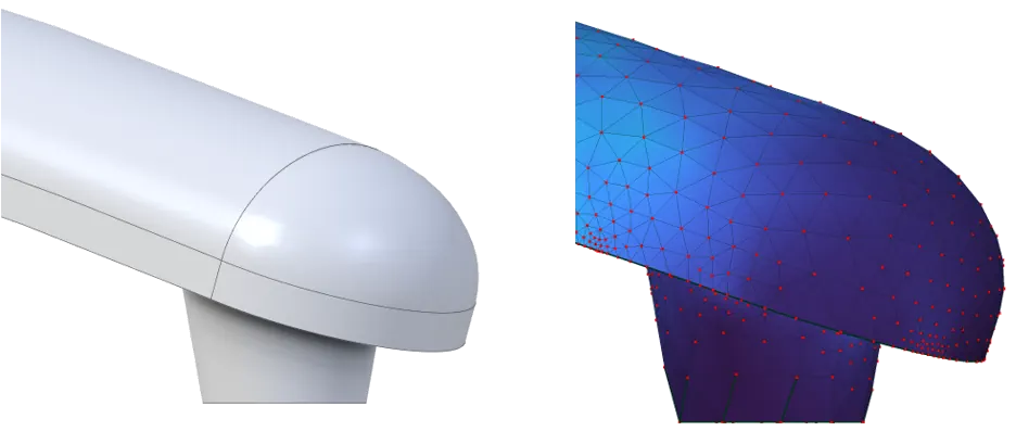
It is difficult to calculate complex geometry that is curvy and organic, but calculating stress through triangles is much easier and more straightforward. Below, you can see a curved object that would be difficult to calculate by hand. We break this object into approximating triangles, with red points where the corners meet. These points are called ‘nodes’, and we can calculate the stress at each of those red points. This allows us to break the problem down into small, or finite, chunks - "finite elements". Several kinds of mesh can be generated.
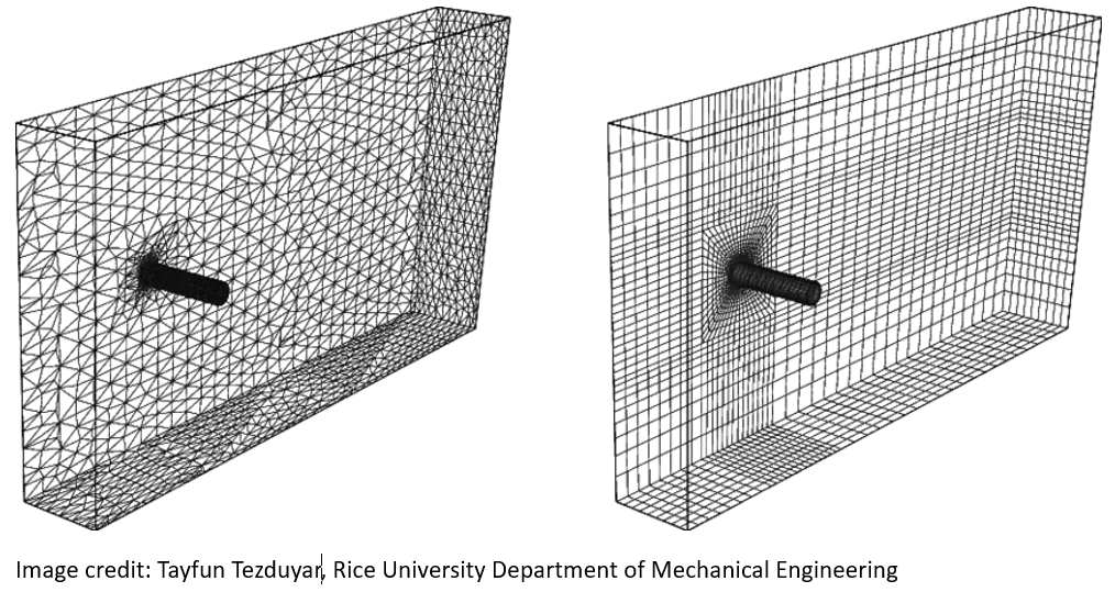
Tetrahedral meshes use triangular elements (left), whereas hexahedral meshes use square elements. In most cases, hexahedral meshes are most desirable as they have high accuracy. Triangles tend to be a strong and rigid shape, subsequently items that have been meshed with tetrahedral meshes may have a greater rigidity than they actually have. However, tetrahedral meshing will fit complex, organic geometry more effectively than hexahedral. Tetrahedral is also available in more programs than hexahedral is.
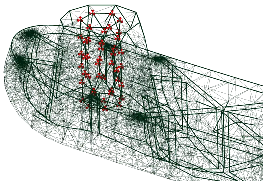
Meshes are exponential in nature—the more mesh elements you add, that is, the smaller the triangles, the more computation is exponentially required to arrive at a result. Because of the correlation of mesh size and computation, there is much discussion about what the best mesh size is. For most cases, try to choose a mesh size that doesn’t sacrifice in the quality or resolution of the study but does not take excessive periods of time to solve.
Meshes are exponential in nature—the more mesh elements you add, that is, the smaller the triangles, the more computation is exponentially required to arrive at a result. Because of the correlation of mesh size and computation, there is much discussion about what the best mesh size is. For most cases, try to choose a mesh size that doesn’t sacrifice in the quality or resolution of the study but does not take excessive periods of time to solve.
Boundary Conditions
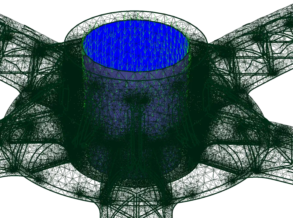
Boundary conditions are fundamental inputs to define the analysis. They are conditions we can apply to nodes or a face that tell the analysis what forces to use, what to hold steady, even what temperature something should be. In this example, lets analyze this chair base:

We need to tell the FEA what geometry will not move. The faces that interact with the chair wheels will be fixed for the purposes of this analysis. We can do that using a boundary condition, telling the analysis software that these faces or nodes will not move; they are fixed geometry. Some boundary conditions can even reflect restrictions in some directions but not others.
To have a complete analysis, it is also important to simulate a person sitting in the chair. We can add another boundary condition that states a force of a person sitting down. We can select the face that will be bearing the load from the chair, and adding the force in a downward direction:
Material Definitions
We also must define what material to use in our study. Here are some of the most common and important properties:
Density: Analyzing mass and weight of components and considering inertia when the study has moving components.
Elastic properties
Young’s Modulus: Also known as the modulus of elasticity, it measures the stiffness of the material or its ability to temporarily deform.
Poisson’s Ratio: A ratio that is crucial for the analysis to understand how a material expands or contracts in different directions when stressed.
Strength
Yield Strength: The stress at which a material begins to deform plastically. A plastic deformation means a permanent deformation.
Ultimate tensile strength: The maximum stress a material can withstand while being stretched or pulled before necking.
Once these properties are entered, an analysis may be run.
Evaluating FEA Solutions
The colors are beautiful, but am I done with the analysis?
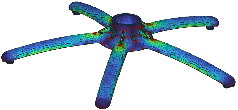
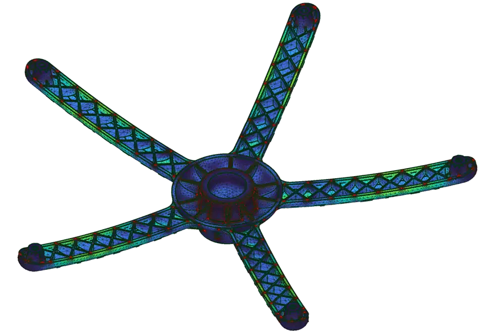
Complex problems can present complex solutions. Once the simulation is run, most programs emphasize a color scale to show areas of stress and deformation. You may also see an animation that exaggerates the part deforming- this is a visual check to make sure the analysis is producing expected results and has been setup correctly. Many FEA simulations also output reaction forces, and an important first step in seeing the results is to take the net of the reaction forces and see if they completely counteract the input forces. If not, there may be an error in the simulation somewhere.
The color scales are meant to show areas of highest stress or deformation, but usually not to indicate if things fail or pass. No matter how good the results look, FEA is only part of the equation. A serious FEA analyst should have some mathematical modeling done by hand to support the FEA findings.
The color scales are meant to show areas of highest stress or deformation, but usually not to indicate if things fail or pass. No matter how good the results look, FEA is only part of the equation. A serious FEA analyst should have some mathematical modeling done by hand to support the FEA findings.
The Role of FEA in Engineering and Computational Mechanics
In engineering, FEA plays a critical role in design and testing. It enables engineers to assess the structural integrity and durability of materials and components before physical prototypes are built.
Applications of FEA in Structural Analysis and Stress Testing
FEA is widely used for structural analysis in buildings, bridges, and even in the design of machinery parts. Stress testing through FEA helps in identifying weak points or stress concentrations in a structure.
Finite Element Analysis in Material Properties and Dynamics
Understanding how different materials behave under stress, heat, or other conditions is essential. FEA aids in analyzing these properties, ensuring safer and more efficient designs.
Finite Element Analysis vs. Computational Fluid Dynamics
While FEA focuses on structural analysis, Computational Fluid Dynamics (CFD) is used for fluid flow analysis. Both are crucial in fields like aerospace and automotive engineering, or anytime engineering industrial applications are concerned.
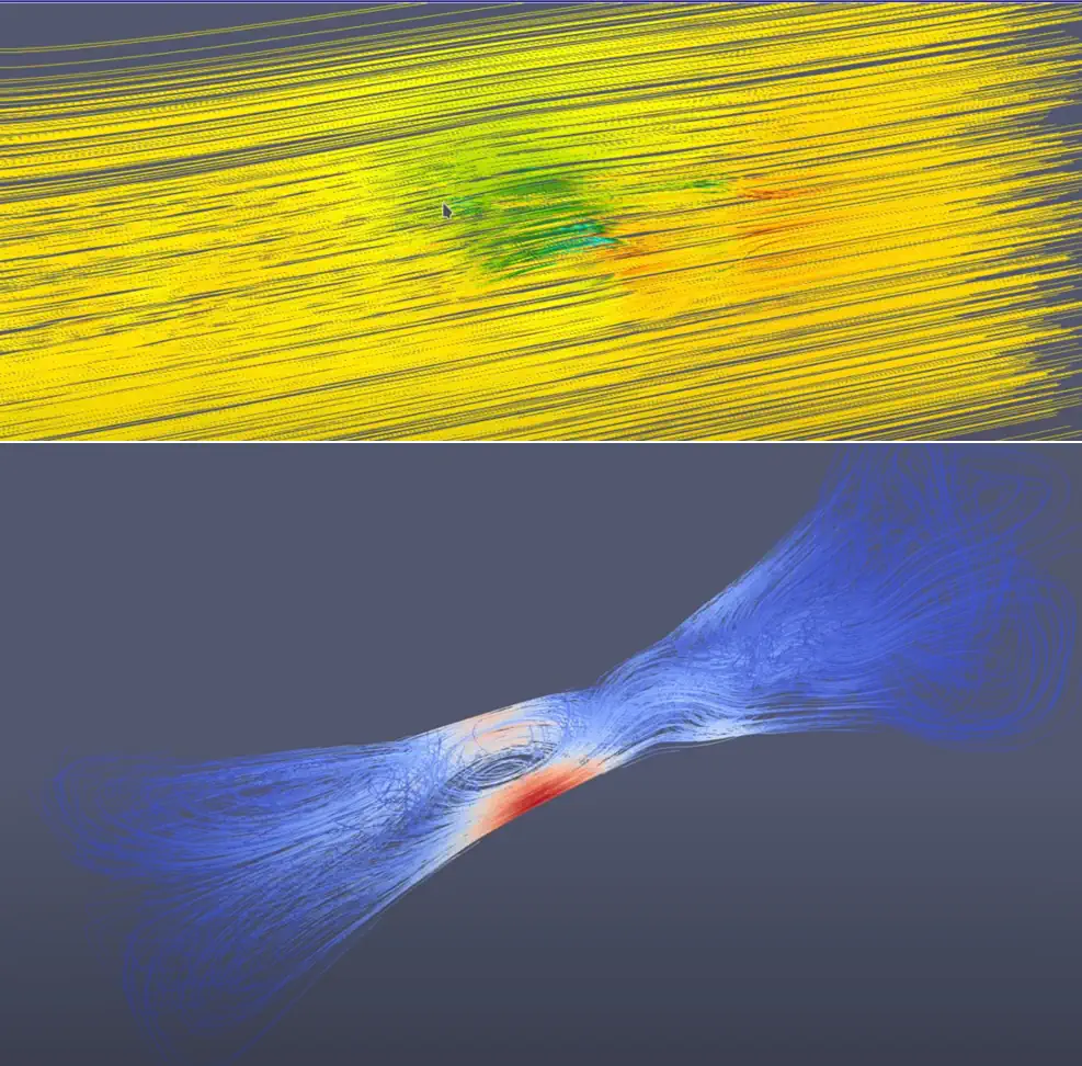
CFD Analysis allows a user to see how a fluid (including air) flows through things like pipes, and it can also display how it externally flows over things like airplane wings.
Solving such flow can be complicated, but CFD is able to perform things such as navier stokes equations that would otherwise be extremely difficult to solve.
To understand the differences between applications:
FEA deals with solid and structural mechanics, and is used for stress, vibration, heat, etc.
CFD focuses on fluid flow dynamics, and is used for analyzing fluid behavior in systems. Fluids in this context are anything that exhibit fluid-like behavior, including gasses.
Advanced Techniques in FEA: From Elasticity to Non-linear Analysis
Finite Element Analysis isn't just about solving simple elasticity problems; it encompasses a range of complex analyses:
Linear vs. Non-Linear Analysis
You may need to analyze material behavior beyond the elastic limit. This is known as non-linear analysis. It can occur for a few reasons, such as:
Non-Linear Material Behavior: The material does not follow Hooke's Law throughout the analysis. Instead, it exhibits behaviors such as plasticity, hyperelasticity, or creep, where the stress-strain relationship is not linear.
Geometric Non-Linearity: Large deformations or rotations occur, significantly changing the geometry of the structure during loading. This alters the stiffness matrix of the system and affects how the structure responds to loads.
Boundary Condition Non-Linearity: Changes in boundary conditions during the analysis, such as contact between components, where the status of contact can change from open to closed or vice versa.
Dynamic Analysis
This involves studying how structures respond to time-varying loads, such as in seismic analysis. This can aid greatly in structural design.
Thermal Analysis
Essential in evaluating the effects of temperature variations on structures and materials.
Real-World Applications and Future Trends in Finite Element Analysis
Finite Element Analysis finds its application in a wide range of industries, from aerospace to civil engineering. Let's explore some of these applications and the future trends in FEA.
Finite Element Analysis in Automotive and Aerospace Industries
In the automotive industry, FEA is used to design safer, more efficient vehicles by analyzing crashworthiness and fuel efficiency. In aerospace, it helps in designing lighter and stronger aircraft components.
The Future of FEA: Innovations and Emerging Trends
The future of FEA looks promising with trends like:
- Integration with AI and Machine Learning: Enhancing predictive capabilities and optimization.
- Sustainable Material Analysis: Focusing on eco-friendly materials and designs.
- FEA Software Advancements: A growing number of providers update software to do things like generative design.
- Integration with AI and Machine Learning: Enhancing predictive capabilities and optimization.
- Sustainable Material Analysis: Focusing on eco-friendly materials and designs.
- FEA Software Advancements: A growing number of providers update software to do things like generative design.
Conclusion: The Importance of FEA in Modern Engineering and Design
Finite Element Analysis (FEA) has become an indispensable tool in modern engineering and design. Its ability to simulate real-world conditions and predict the behavior of structures under various loads makes it invaluable across multiple industries.
The Indispensable Role of FEA in Engineering
FEA allows engineers to:
Minimize Physical Prototyping: Reducing time and costs associated with physical testing.
Enhance Product Design: Enabling the exploration of a broader range of design options.
Improve Safety and Reliability: Helping to identify potential failure points before actual deployment.
Minimize Physical Prototyping: Reducing time and costs associated with physical testing.
Enhance Product Design: Enabling the exploration of a broader range of design options.
Improve Safety and Reliability: Helping to identify potential failure points before actual deployment.
How FEA Shapes the Future of Engineering
The ongoing advancements in FEA are shaping the future of engineering in several ways:
Integration with Emerging Technologies: The integration of FEA with technologies like 3D printing and IoT is opening new frontiers in product development and testing.
Sustainable Engineering: FEA plays a critical role in developing more sustainable and environmentally friendly materials and designs.
Advancements in Computational Power: As computational capabilities grow, so does the potential for more complex and accurate simulations.
Final Thoughts
As we have explored, FEA is more than just a tool for engineers. FEA is a gateway to innovation, safety, and efficiency in design. Whether it's in automotive design, aerospace engineering, or material science, FEA's role is pivotal and ever-expanding. Understanding and utilizing this powerful tool can lead to groundbreaking advancements and efficiencies in virtually any field of engineering and design.