Part Generator

On-Demand Parts

What is the Part Generator?

The Part Generator allows you to add designs to a library alongside design logic and data. You choose what variables you want to expose for real-time customization. When you insert a design from the library, a user interface with the variables you chose will allow you to make quick edits. 

Part Generator Overview Video

The Part Generator is an extremely powerful addition to your design and customization workflow. Achieve design workflows that are orders of magnitude faster than traditional editing.

Part Generator Benefits

Address many design and business challenges with the Part Generator:

Realtime Edits

Parts that you often edit for a particular fit or function can be modified in real-time without traditional editing.

Customization

Quickly make custom variants of a design right in front of a customer while adhering to design rules you define and without tedious clicking.

Variant Creation

Create variants of components while always adhering to core design logic and data.

Reduce Human Error

Design logic and datasets drive the design during editing. Keep custom parts manufacturable and within your desired range of edits. 

Abstract Away Complexity

Parts often have dozens of variables and bits of design logic that would have to be manually edited. The generator turns all of this clicking into a simple, elegant user interface.

Auto User Interface

While inserting a part from the library, a user interface is automatically and dynamically generated that allows you to make changes.

How it Works

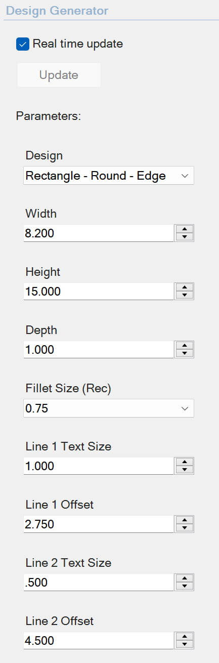
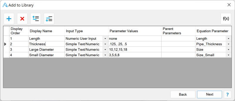
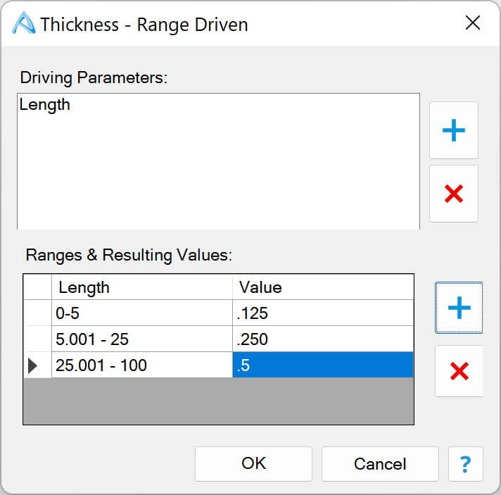
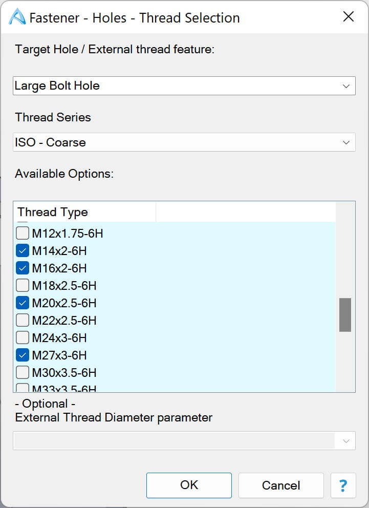
When making a design you define dimension, angles, pattern counts, etc. Each of these values is a variable. While adding a part to the library, you can choose which variables are important enough to be changed during insertion.

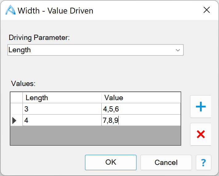
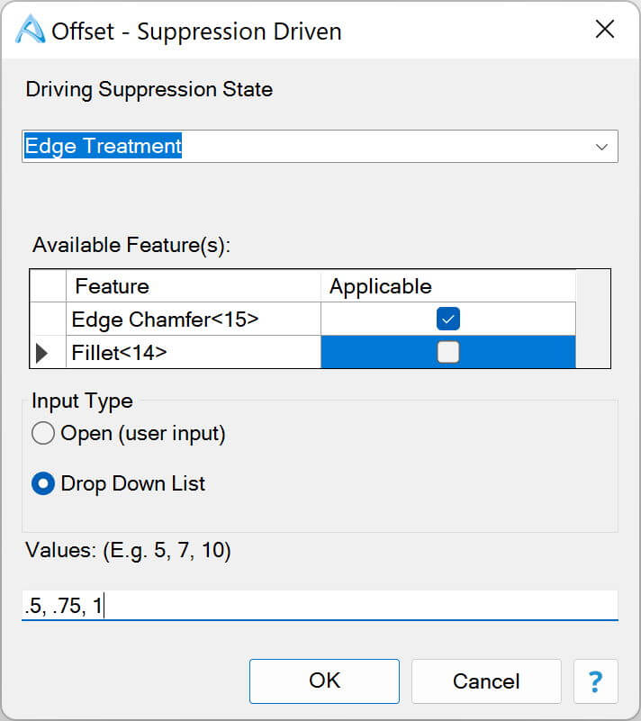
You define what kinds of changes can be made for each variable. For example a user can type in a value or select from a dropdown list. Acceptable values for some variables may change based on the value of other variables.

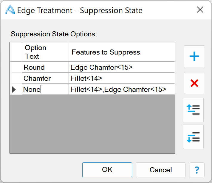
You can also make options to turn on or off multiple features based on a selection.

Data Types

Choose a variety of data types and logic.

Adding to the Library

When adding a component to the library you will determine which variables matter and how they should be treated, as well as add in any data or design logic. In this example, the user can type in a value for the Length but must choose from predetermined variables for the Thickness and Diameters.

Simple Text/Numeric

A simple text / numeric input allows you to define a comma separated list of acceptable alphanumeric values. A user is presented the list of options in a dropdown and can choose the desired value.

Numeric User Input

This data type allows a user to type in a numeric value for a parameter. The entered value is directly reflected in the updated 3D model.

Value Driven

This data type lets you map values from one variable to another. For example, if the value of Length equals 3, the acceptable values for Width are 4,5, and 6. If the value for Length equals 4, the acceptable values for Width are 7,8, and 9. A user is presented the correct set of data based on the value of other parameters.

Range Driven

This data type lets you map ranges of values from one or more variables to another. For example, if the value of Length is between 0 and 5, a Thickness of .125 is used. Between 5 and 25, a Thickness of .25 is used. Between 25 and 100, a Thickness of .5 is used.

You can add additional input variables to create a matrix of acceptable values based on multiple variables.

Suppression State

This data type lets you map feature suppression to values in a dropdown list. In this example, if the user chooses the Chamfer option, we will suppress the fillet. If the user chooses Round, we will suppress the chamfer. If the user chooses None, we will suppress them both.

Suppression Driven

This data type lets you map the results of a Suppression State data type to available values based on whether certain features ended up getting enabled or disabled. In this example, if the user chooses an option in the Edge Treatment Suppression State data type that results in Edge Chamfer<15> being enabled, we will provide the user with 3 options for an offset value: .5, .75, and 1.

Threads

This data type lets a user pick from the selected thread types for a target hole or external thread feature. In this example, we have a feature called Large Bolt Hole, and we've defined 4 acceptable thread values that a user can choose from a dropdown list.

For external thread features, you can optionally choose a parameter that changes the diameter of the external thread's cylinder to ensure the geometry matches the thread.
Copyright © Alibre, LLC